Efficiency and Power in Servo Drives
Overview
This document explains the origin of power losses in DC servo drives, it proposes a method for calculating its efficiency and it gives some recommendations and guidelines to follow in order to increase it.
In the process of converting electrical energy to mechanical energy, all the elements in between the input electrical power and the output mechanical power present power losses, in the form of heat dissipation. The servo drive's electronics (the logic system and the power stage), the power cables, the motor windings, and the motor mechanical losses are some of the sources of power losses in this energy transformation from electrical to mechanical. The following diagram depicts the power flow and its losses.
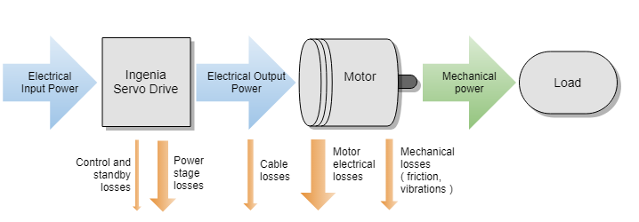
Power losses not only increase the power consumption of the system but are transformed into heat. System heat must be evacuated since a rise in temperature worsens system operation (increases the power losses, components drift, and electrical noise) and reduces the life expectancy of the components. Furthermore, heat evacuation measures are expensive and do complicate high-density integrations and size reductions. For all these reasons, the minimization of power losses should always be an objective in a servo driven system.
Efficiency
The efficiency (η) is defined as the ratio between the output mechanical power (Pout) and the input electrical power (Pin).
η = Pout/ Pin
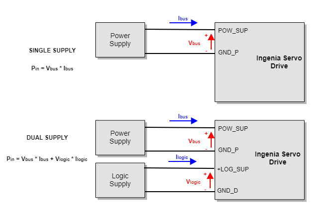
In a DC servo-driven motor, the input power is the electrical power provided by the power supplies or battery systems. When a single supply is used, Pin can be calculated as:
Pin = Vbus * Ibus
where Vbus is the power supply DC voltage (between POW_SUP and GND_P terminals) and Ibus is the current provided by this power supply.
However, when the servo drive uses a dual supply source (different supply for power and logic), both supplies must be considered. In a dual supply system, Pin can be calculated as:
Pin = Vbus* Ibus + Vlogic * Ilogic
where Vlogic is the logic supply voltage (between +LOG_SUP and GND_D terminals) and Ilogic is the current provided by the logic supply.
The output power is the mechanical output power provided by our motor, defined as:
Pout = ωout * τout
where ωout is the output rotatory velocity in rad/s and τout is the output torque in N·m.
Power Losses in a Servo Drive
All the elements in the system have losses, and therefore, contribute to the heating of the system. Mechanical losses are mainly generated on the bearings and gears, and motor losses are mainly composed of resistive losses on the windings and the magnetic losses on the core. For further information about mechanical and motor losses, please refer to the manufacturer's data.
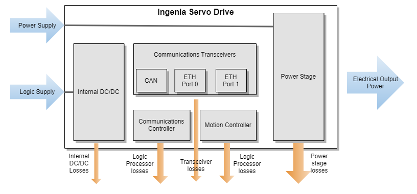
Power losses in servo drives are mainly caused by the power stage, which converts from a DC input supply to an AC output voltage. However, other blocks in the servo drive contribute to the power losses. The image shows a block diagram of the main power losses sources in a servo drive.
Power Stage
The power stage is, without any doubt, the main source of power losses in a servo drive. In servo drives for three-phase motors, the power stage consists of six transistors that convert a DC input supply to an AC output motor voltage. Each pair of transistors (known as a half-bridge) switches complementarily generating a Pulse Width Modulated (PWM) output voltage. Since the motor windings are mainly an inductive circuit, when applying high-frequency PWM (from 20 kHz to 200 kHz), the voltage becomes filtered and generates a continuous current. Each half-bridge excites a motor phase with a different ON-time to period ratio (duty cycle), generating different average output voltages, and therefore, causing a current flow through the motor. When the duty cycle varies with time, the output voltage can become a low-frequency AC signal.
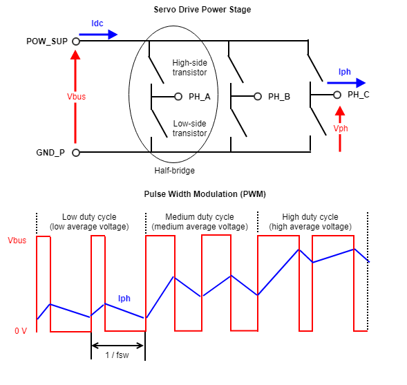
The current flow through the transistors generates what is called conduction losses, while the activation and deactivation of the transistors generate what is called switching losses.
The Ingenia Servo Drives are based on transistors which can be modeled as voltage-controlled resistors; when the transistor is activated, the resistance is very small (known as Rdson) and the current flows through the transistor; when the transistor is deactivated, the resistance is very high and it can be considered as an open-circuit. Conduction losses (Pcond) are the losses generated on the Rdson resistors. Since there is always one transistor per half-bridge activated, the total conduction losses per phase can be modeled as:
Pcond = Rdson * Iph2
where Iph is the phase output current.
The Rdson is not constant but increases with temperature. Therefore, the higher the temperature, the higher the power losses. It is very important to correctly dissipate the servo drive in order to reduce its power losses.
When a transistor is deactivated, it handles a high voltage between its terminals while the current is zero. And when it is activated, it can flow a high amount of current while the voltage in its terminals is very small.
The normal operation of the transistors is to have a high voltage between its terminals when the current is zero (transistor deactivated) or having a very small voltage drop (Rdson) when the current is high (transistor activated). However, the switch between the two states is not instantaneous and during this process, both high current and high voltage are present between the transistor terminals at some points. This causes a high amount of instantaneous power losses during a very short period of time (< 100 ns). The Switching Losses (Psw) are defined as the average of instantaneous power losses. The instantaneous loss of each commutation is proportional to the power supply voltage (Vbus) and to the phase current (Iph). The switching losses are also proportional to the number of commutations per second, that is, to the switching frequency (fsw).
Psw ∝ Vbus, Iph, fsw
Internal DC/DC
The input logic supply voltage provided to a servo drive (i.e. 24 V) is not appropriate for supplying internal electronics. For this reason, all the Ingenia Servo Drives include internal DC/DC converters that adapt the logic supply source to the required internal voltages (i.e 5V, 3.3V, or 1.2V).
The internal DC/DC converters are based on small power converters, containing only one or two transistors. Like the power stage, the DC/DC converters generate a PWM voltage that is filtered to achieve a continuous DC voltage and current. In order to reduce the size of the DC/DC converter and the filtering elements, DC/DC converters switch at a very high frequency (from 150 kHz to 2 MHz). Due to the high-frequency, main DC/DC losses are caused by switching losses, which are proportional to the input voltage.
Even when using cutting-edge technology, small and compact DC/DC converters have maximum efficiencies between 90 to 95%. This means that up to 10% of the input logic power can be lost in the voltage conversion to power the internal circuitry.
Logic Processors
All the power consumed by the logic processors included on a servo drive (Motion Controller, Communications Controller, etc) can be considered power losses since they are not provided to the output mechanical power. The higher the processing capabilities of a servo drive are, the higher its processing losses.
These losses are minor when compared to the power stage losses at maximum current, but are very important when considering the standby power losses.
Communication Transceivers
The logic transceivers managing fieldbus communications are other power losses and heat generation sources. As many communication channels are connected/activated at the same time, the higher are the losses. In some communication interfaces, like Ethernet, the single presence of point-to-point connections, even if no messages are sent, generates power losses.
Standby Power Losses
The standby power consumption refers to the input power consumption when no power is provided to the motor. In applications where motor movement is not constant and current on the motor is usually null, standby power losses are critical.
In some applications, the standby power losses require to maintain motor control even if the output current is zero. That is, handling a motor position with no external torque. For this reason, Ingenia defines standby power losses as power consumption when:
Communication is active
Motion Controller is active, with all the loops at maximum frequency
DC-bus voltage is supplied.
The power stage is enabled and switching.
The output current is zero.
Power Losses Reduction
The following are some recommendations to maximize the efficiency of the servo drive(s) in our system:
Dual supply: Whenever possible, use a dual supply topology, with different voltage values for the power supply and the logic supply. The dual supply allows using a lower supply voltage for the internal DC/DC input, improving its efficiency.
Minimum Logic Supply voltage: Generally, the logic supply is only used for supplying the internal DC/DC. In that situation, using the minimum voltage supply does not have any drawbacks. If the logic supply is used for other functions (like supplying the electro-mechanical brake), use the minimum voltage required for the other functions.
Minimum Power Supply voltage: Switching losses of the power stage are proportional to the power supply voltage. Analyze the minimum voltage required for your speed and acceleration requirements in your application and use it for increasing efficiency.
Minimum Switching Frequency: Switching losses are also proportional to the servo drive switching frequency. Therefore, use the minimum voltage frequency required by our motor inductance and control loop update rate requirements.
Reduce communication ports: The use of multiple communication interfaces increases logic consumption. Use only the communication interfaces or ports that are really needed at any given time.
Provide good heat dissipation: The power losses increase the temperature of the components, which will generate higher losses the higher the temperature is. Improving the heat dissipation will reduce components temperature, and therefore, its losses.
Power Losses Estimation
Power Losses Estimation from Product Manual
As explained above, the calculation of the servo drive losses is complex and depends on many factors. For this reason, the best way is to obtain the servo drive power losses from the Product Manual. Ingenia servo drives provide graphical and numerical representation of the power losses on the Product Manual / Product Description / Thermal and Power Specifications. The following is an example of Everest XCR servo drive:
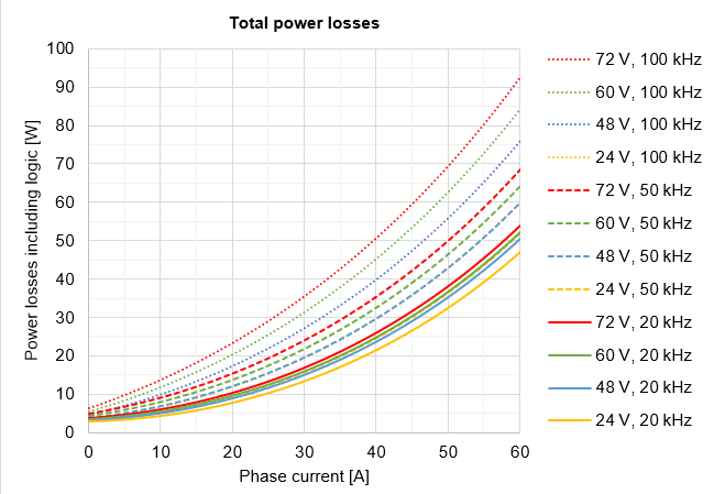
The losses depend on the phase current provided to the motor (Iph), the power supply voltage (Vbus), and the switching frequency (fsw).
Current crest value, not RMS
Notice that current Iph is expressed in crest value for a 3 phase BLAC motor. For further clarifications and conversion to equivalent RMS values please refer to Disambiguation on current values and naming for Ingenia Drives.
Phase current Iph
To calculate the servo drive losses, calculate which is the motor phase current required by your application. The phase current (Iph_mot) is proportional to the motor torque (τmot). The motor parameter "torque constant" (usually named Kt) determines how much torque (N·m) is generated per ampere of input current to the motor. Therefore, if the required torque is known, the phase current can be estimated.
Some motor manufacturers define the torque constant Kt as the ratio between torque and crest current (amplitude of a sinusoidal), while others define Kt as the ratio between torque and RMS current. Please, check your motor manufacturer for this information. Ingenia always use crest current for calculating power losses in 3-phase BLAC motors.
If Kt is defined for the crest current, motor current Iph_mot can be estimated as:
Iph_mot = τmot/Kt
If Kt is defined for the RMS current, motor current Iph_mot can be estimated as:
Iph_mot =√2 * τmot/Kt_rms
These equations are only approximations. Different factors like motor losses or temperature can affect to the ratio between torque and phase current.
In Y-wired BLAC motors, Iph_mot equals to the servo drive current Iph required for calculating the losses:
Iph = Iph_mot-Y
However, in Δ-wired BLAC motors, the servo drive current is √3 times bigger than motor phase current
Iph = √3 * Iph_mot-Δ
Supply voltage Vbus
In order to optimize the power losses, use the minimum power supply voltage required by your system. The supply voltage defines the maximum AC phase voltages that can be provided to the motor, which defines the maximum speed that can be reached by the motor in nominal operation. To calculate the voltage required, we have to consider the simplified electrical model of a motor, where each phase is composed of a resistor, an inductor and a back-electromotive force (BEMF), modeled as an electrical source:
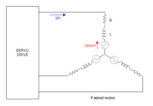
Similar to the torque and current, the motor parameter "velocity constant" (usually named Ke or Kω) determines the BEMF voltage (VBEMF) generated by the motor at a certain speed (ωmot).
VBEMF =ωmot/ Kω
The current flow through the motor (and therefore the torque) depends on the difference between the phase voltage and the BEMF voltage. If the phase voltage is lower than the BEMF, current and torque will be reduced, slowing down the motor. If the phase voltage is higher than the BEMF, the motor will generate torque, accelerating the motor or maintaining the velocity. Note that the acceleration will depend on the difference between generated torque and torque losses (load and friction).
Calculating accurately the voltage value needed, requires to solve the complex electrical model. Further details can be found in the following article:
For simplification, we will not consider the voltage drop in the motor resistance and inductance, calculating the minimum power supply voltage without considering torque.
In a Y-wired BLAC motor, VBEMF is provided phase-to-neutral. Considering that VBEMF is measured in RMS value:
Vbus > VBEMF_Y * √3 * √2 / Dmax
where Dmax is the maximum duty cycle that can be provided by the servo drive. This value is also expressed as "Bus voltage utilization" in the Product manual / Product Description.
In a Δ-wired BLAC motor, VBEMF is provided phase-to-phase. Considering that VBEMF is measured in RMS value:
Vbus > VBEMF_Δ * √2 / Dmax
For further information about the voltage and current relations in Y- and Δ-wired motors see the following article:
Switching frequency fsw
The third parameter required for calculating the power losses is the switching frequency fsw. Switching frequency usually ranges from 20 kHz to 100 kHz (some drives can reach up to 200 kHz) and can be configured by the user. Like with the power supply voltage Vbus, it is recommended to use the minimum switching frequency that allows the desired performance of the system.
The choice of the switching frequency is related to the current loop frequency and to the inductance of our motor (the smaller the inductance, the bigger the switching frequency must be). For detailed information on choosing the switching frequency, please see the following article:
Heat Dissipation
To minimize the temperature rise in the servo drive, the system heat must be properly dissipated. Once the power losses are calculated, the heatsink requirements can be determined. The following diagram depicts a simplified dissipation model for the Everest XCR Servo Drive.
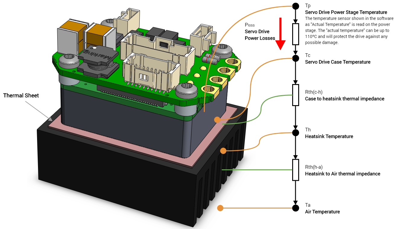
The power losses generated by the servo drive flow from the power stage to the air. The resistance of the different materials to the conduction of heat (known as thermal impedance, Rth) generates a temperature difference between the air and the power stage. If we know the power losses (Ploss), the thermal impedances (Rth), we can determine the temperature that will reach the power stage.
The thermal model of a power stage is complex, with multiple heat sources (multiple transistors) and considerations. To avoid using complex models between the power stage to servo drive case impedance (Rth(p-c)), Ingenia provides the maximum temperature that can be reached on the case (Tc). These temperatures can be found on the current derating graphs (see Product Manual / Product Description / Current Derating). See an example for the Everest XCR servo drive:
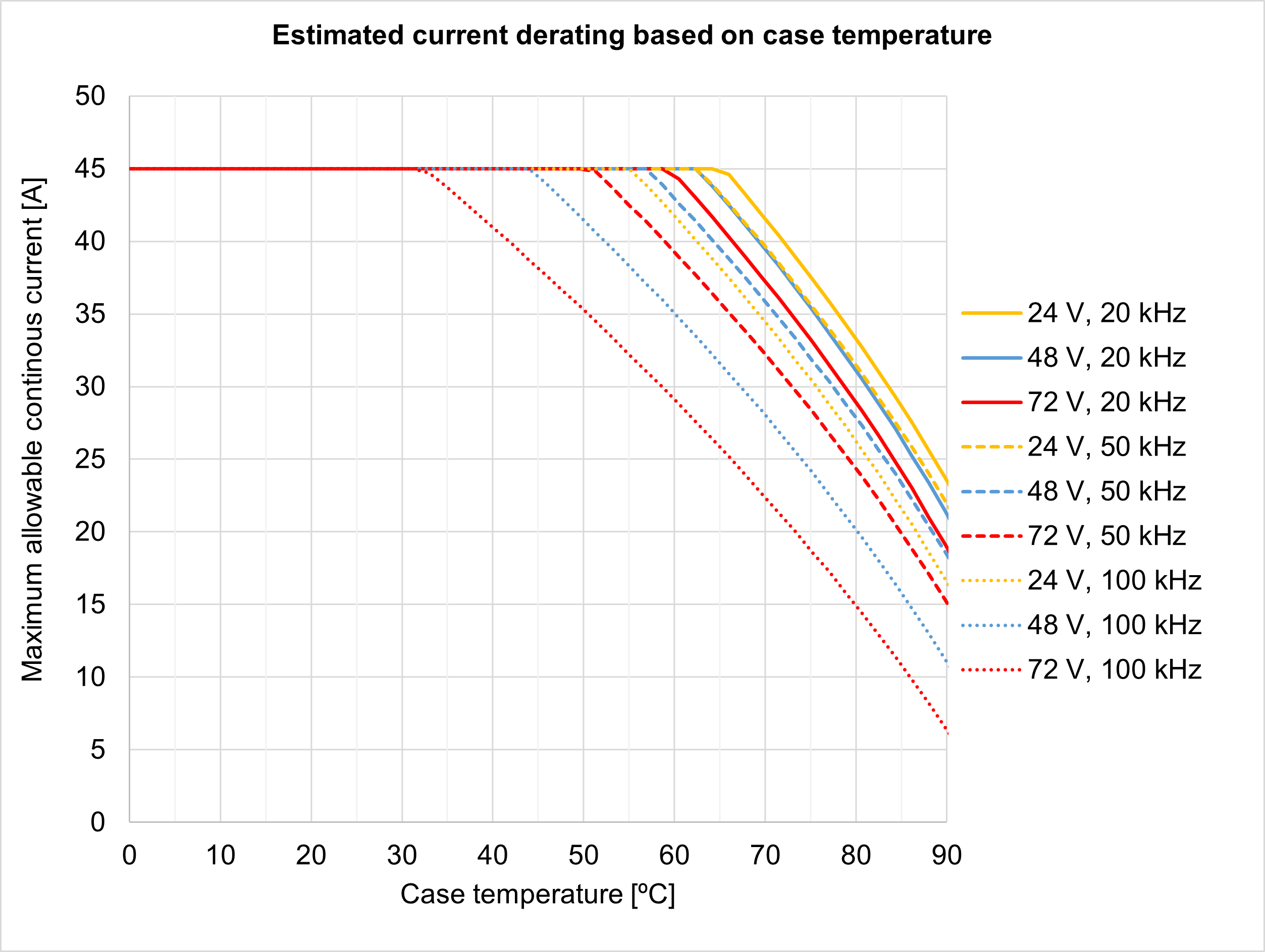
This graph defines the maximum temperature of the servo drive case (Tc) for different power supply voltage (Vbus), phase current (Iph) and switching frequency (fsw).
Once defined the maximum case temperature (Tc), and the system power losses (Ploss), the required heatsink can be calculated. Ingenia servo drives are designed to be mounted on a cooling plate or heatsink to achieve its maximum ratings. See the Product Manual / Installation for further details about the assembly.
Please, use the following procedure to determine the required heatsink:
Based on the power supply voltage (Vbus), the phase current (Iph) and switching frequency (fsw) required by your application, determine the maximum Case temperature Tc that can be handled.
For example: If the application requires 30 A @ 72 V (20 kHz) the Tc will be 85 ºC
Based on the power supply voltage (Vbus), the phase current (Iph) and switching frequency (fsw) required by your application, determine the Power Losses Ploss to be dissipated.
For example: If the application requires 30 A @ 72 V (20 kHz) the PL will be 25 W
Determine the Thermal impedance of the used thermal sheet Rth(c-h)
For example, a thermal sheet TGX-150-150-0.5-0, which has an estimated thermal impedance of Rth(c-h) = 0.2 K/W
Based on the ambient temperature (Ta) and using the following formula determine the maximum thermal impedance to air of the required heatsink Rth(h-a)
Rth(h-a) ≤ (Tc + Ploss * Rth(c-h) - Ta) / Ploss
For example: If the application requires 30 A @ 72 V (20 kHz) working at Ta = 25 ºC and we use a thermal sheet with Rth(c-h) = 0.2 K/W the required thermal impedance of the heatsink will be Rth(h-a) = 2.6 K/W
Efficiency and Power Experimental Measurement
According to the previous definitions, the efficiency of a servo drive is defined as the ratio between the power provided to the motor (Pmot) and the input power (Pin).
ηdrive = Pmot/ Pin
To measure efficiency experimentally, servo drive output and input power must be measured. Input power can be easily calculated as the product of input voltages and currents. These are continuous magnitudes that can be measured with standard laboratory instruments.
Pin = Vbus* Ibus + Vlogic*Ilogic
Servo drive output power can also be calculated as the product of the phase voltages and currents. Since servo drive outputs are AC signals, the average power for a cycle must be used:
Pmot=1/T * ∫(Va⋅Ia+Vb⋅Ib+Vc⋅Ic)dt
If the phase currents and voltages were simplified to sinusoidal AC signals, a good approximation to the motor power could be achieved (see How to calculate the output power of a Servo Drive for further information about this approximation method). However, this method does not consider the non-idealities of the power stage (PWM switching, the voltage drops in the transistors, etc.), which are the cause of the power losses. Therefore, the sinusoidal approximation is not valid for calculating the servo drive efficiency.
Since the sinusoidal approximation is not valid for measuring efficiency, higher accuracy measurement methods have to be used. Two methods are analyzed and its requirements detailed: the use of a three-phase power analyzer and the use of a calorimeter with a calibrated thermal impedance.
Three-phase power analyzer
The easiest way of measuring the servo drive output power (Pmot) is to use a multi-channel power analyzer. This instrument measures the three phase voltages and the three phase currents of the motor and multiplies them, calculating the instantaneous power losses and averaging them. In principle, this should be the most accurate way to measure the servo drive output power. Since power losses in a servo drive are only a small fraction of the output power (efficiency could be around 97%), the power measurement has to be very accurate. That is, an accuracy of 1% in the power measurement can imply an error of 50% in the power losses. Due to this fact, the accuracy and sampling frequency required for measuring the servo drive efficiency are too demanding for most commercial power analyzers.
The voltage meters included on the power analyzer must be able to accurately measure the voltage drop in the power stage transistors in order to measure conduction power losses. Considering a transistor on-state resistance (Rdson) of 3 mΩ when providing a current of 30 A, it causes a voltage drop of 90 mV. Considering that phase voltage is a PWM signal swinging from 0 to 72 V (Vbus voltage) a normal scale for the voltage meter could be 100 V. With these considerations, and limiting to 1% of error of the measured voltage, the voltage meter requires accuracy of 0.01% of full scale at 100 V. This is a very demanding requirement not fulfilled by most commercial power analyzers.
The sampling rate of the power analyzer is as critical as the voltage accuracy. To correctly measure the output power, the duty cycle (percentage of time during the signal is high) of the output signal must be correctly measured. For a switching frequency of 100 kHz, (10 µs of period) a minimum sampling rate of 10 ns is recommended, which means a 0.1% accuracy of the duty cycle. This is also a very demanding requirement, not fulfilled by most power analyzers.
Calibrated thermal impedance
Instead of measuring the output power and finding the efficiency, an easier approach is to directly measure the power losses, and after that, calculating the efficiency:
Pmot = Pin - Ploss
ηdrive = (Pin - Ploss)/ Pin
A method for measuring the power losses is to measure the heat generated. To do it, a setup with a known heat transfer path is required. The proposed setup consists of a calorimeter with a small dissipation aperture. On the heat conduction path (implemented in an aluminum block) we place two temperature sensors on different points of the path. If the thermal impedance between the two points is known, the temperature difference will provide a measure of the power that is being dissipated.
Note that a minimum dissipation is required to achieve a thermal steady state below the maximum temperature of the drive. If the dissipation is too small, the drive will reach excessive temperature and will stop operation (overtemperature protection).
The following diagram shows the proposed setup.
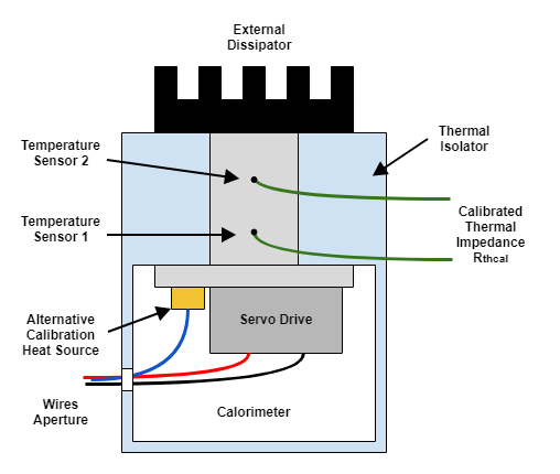
Before each use of the setup, the thermal impedance Rthcal must be calibrated using a known thermal source. The most accurate way of doing it is by generating heat on the reverse diodes of the power stage. If a negative voltage is applied between phases and GND, a current would flow through the diodes, generating losses. Be careful, if not properly done, this method could damage the power stage!
An alternative method is to place a known power resistor on the same dissipation plate than the servo drive. To achieve an accurate measure, the resistor must be placed very close to the servo drive and must have a similar thermal coupling with the dissipator.
Apply a constant voltage to the calibration thermal source and measure the current and voltage applied to determine the power. To achieve proper calibration, the generated power (Pcal) must be similar to the servo drive power losses (Ploss). While applying the calibration power, measure the temperature on the sensors 1 (T1) and 2 (T2). Once the temperature has reached the steady-state, record the values of input power (Pcal), and the temperature T1 and T2. After this test, the thermal impedance can be calculated as:
Rthcal = (T2-T1) / Pcal
After the calibration, the power losses can be measured. Supply the servo drive at the desired power supply voltage (Vbus) and excite the motor at the desired phase current (Iph). Maintain the tested conditions until reaching a thermal steady-state. At that point, measure temperatures T1 and T2 and calculate the servo drive power losses:
Ploss = (T2-T1) / Rthcal
Conclusions
The main article conclusions can be summarized in the following points:
All the elements in a servo actuator generate power losses. The power losses are transformed into heat, which worsens the system performance. Therefore, power losses must be dissipated.
Power losses dissipation complicates system integration. The best approach is to minimize the power losses.
The main source of power losses in a servo drive is the power stage. However, logic processors and internal DC/DC also contribute.
Standby power consumption is the input power when no power is provided to the motor, but PWM switching is still active.
To reduce the servo drive power losses use a dual supply scheme (logic and power), use the minimum required supply voltage, use the minimum required switching frequency and provide good thermal dissipation.
Guidelines for estimating the power losses and calculating the heatsink requirements have been provided.
Efficiency measurement with power analyzers is difficult since the accuracy and sampling rate requirements are too demanding. Power losses can be measured with a modified calorimeter with a calibrated thermal impedance.