Digital Halls
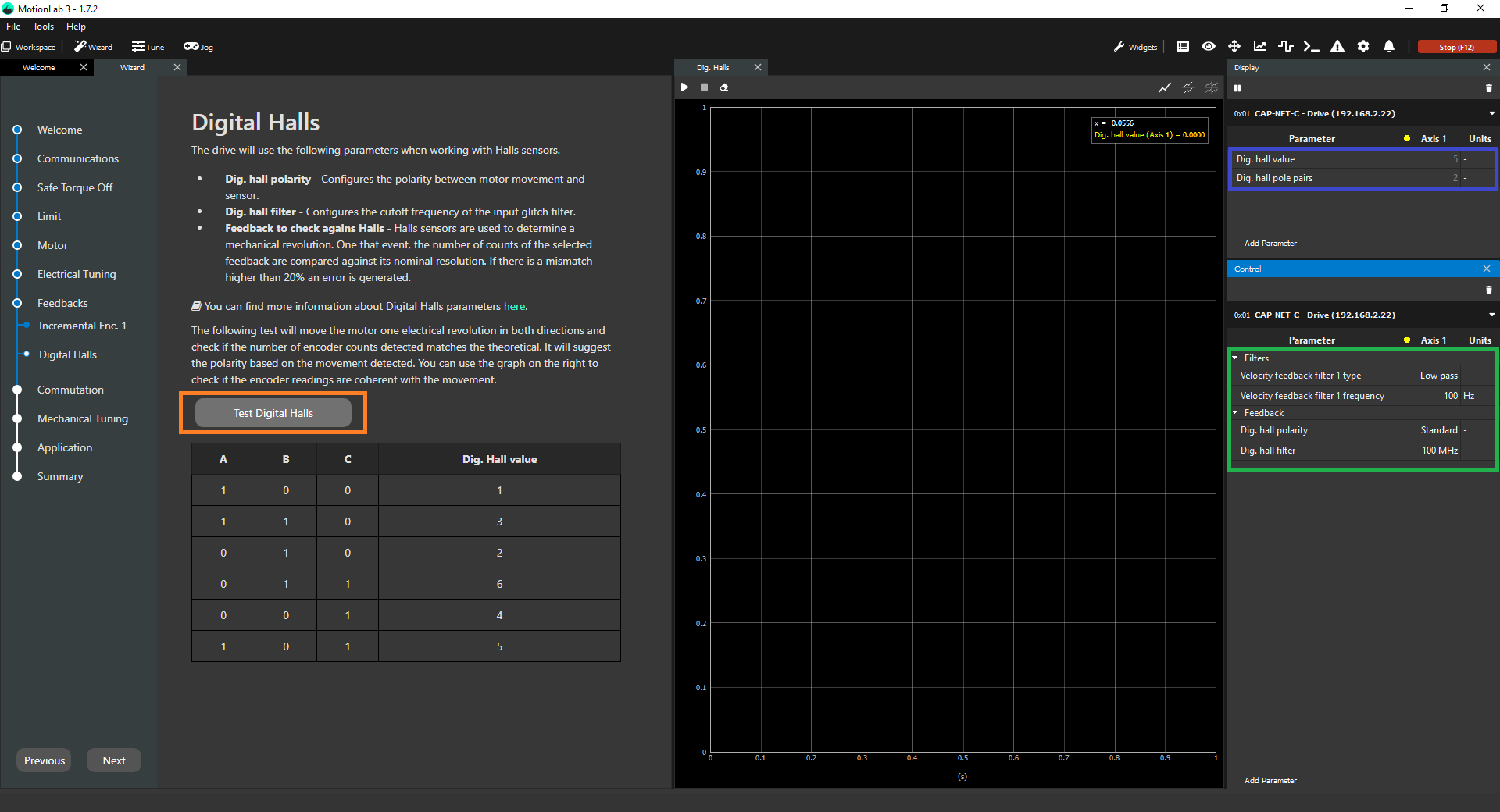
This step explains how to configure the digital halls properly in the configuration Wizard. To do it, you need to properly fill in the parameters associated with this sensor in the Control widget (green square below). After this, you can validate that the position readings are correct both by taking a look at the values in the Display widget (blue square below) and performing the digital halls test (orange square below) to make sure that the hall readings and pole pairs settings of the motor are correct.
If you are interested in learning more about the parameters configured in this step, please refer to the firmware manual documentation: Digital halls.
Parameters to configure
Dig. hall filter → Glitch filter levels of the digital halls module. There are 10 different glitch filter levels. Each level corresponds to a specific cut-off frequency. Setting this register parameter to 0 (100 MHz) will disable the glitch filter.
Dig. hall polarity→ The polarity of the feedback sensor is a parameter that relates to how the position readings change when a positive voltage is applied to the phases of the motor. It can either be "Standard" or "Reversed".
Understanding how the polarity works
If with polarity set as "Standard, the position increases when a positive voltage is applied, then the polarity is correct as "Standard". On the other hand, if the position readings were to decrease, then the polarity setting would be wrong and you would need to change it to "Reversed" for this particular feedback sensor. Having a correct polarity setting is essential to having the sensor working properly and this is exactly what the digital halls test is meant to determine. On an additional note, the polarity of the digital halls does not relate to the polarity of any other feedback sensor in the system (they can be the same or opposite, it does not matter).
Digital halls test
This test has the following purposes:
Validate that the digital hall readings are correct → This is done by moving a certain predefined range of motion and counting the position readings so if they match with the expected ones then the test turns successful. If they do not match, then you get a failure and you need to recheck both parameters to see which one could be wrong. In this particular case, the algorithm perform its calculations with the set pole pairs, so the only chance of this test failing is when either the current loops are not tuned properly, the hall sensors are not being read correctly or the motor is loaded.
Validate that the pole pairs parameter are correct → This is configured in the Motor settings and it is used to perform the test motions. A visual check of the movements must be carried out to ensure the correct configuration of the pole pairs parameter. Three movements must be observed: first, an alignment movement; second, a full revolution in one direction; and a final full revolution in the opposite direction. A visual check of latter two movements (two full revolutions in each direction) is advised as the test will not fail if this parameter is wrongfully set.
Determine the polarity of the digital halls → This is done by applying always positive voltage first and then negative voltage and seeing how the position readings change. Please note that this polarity determination is not done if the previous validation does not turn out successfully.
Therefore, this test has only two possible outcomes:
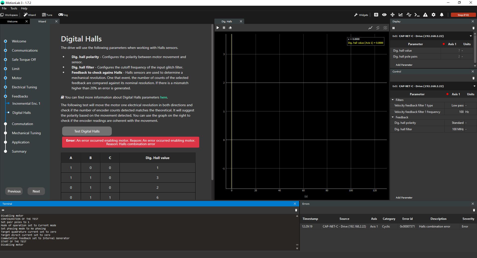
Failed test
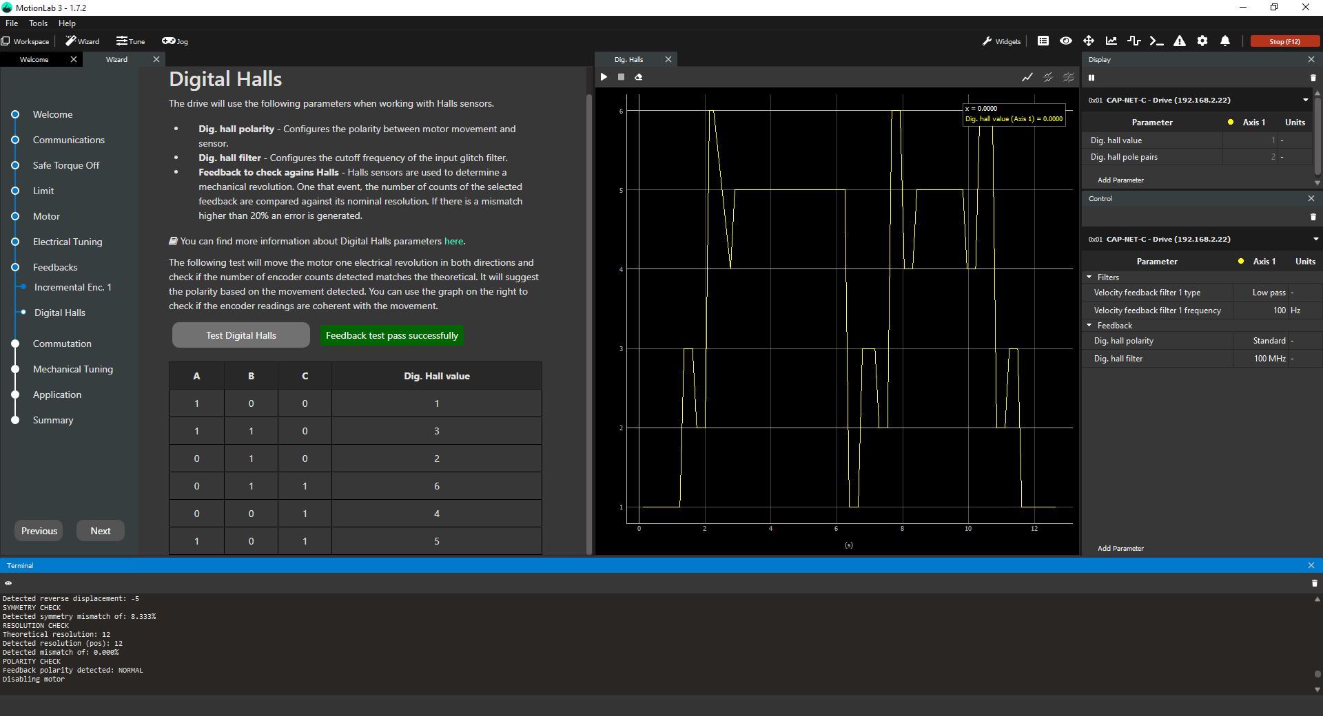
Success test
Digital halls quick verification
If you get a failure in this test, a quick check that you can do is verify that the hall position readings along a whole mechanical revolution are correct according to the pole pairs of the motor. You need to move the shaft manually one full revolution (motor is disabled) and check that the values of the halls (blue square in the initial picture) change a number of (6*number of pole pairs) times. If they do not, then your pole pair parameter is wrong. In a system with a gearbox, this can be trickier but you could move the motor in voltage mode (using the Jogs) and check that a full revolution on the output equals an increment in position readings equal to (6* number of pole pairs * gear ratio of the gearbox).
Once you get a success message in the digital hall test, you can proceed to the next step.