Setting up an FSoE application with TwinCAT
By default, the STO and the SS1 are enabled on the drive. Unless they are configured correctly and released simultaneously, the drive will not allow any movement.
This guide gives you an example on how to configure the TwinCAT main device in order to operate the STO and the SS1 correctly.
Page contents:
Background
This guide provides step-by-step instructions for creating a basic Safety Application with a Novanta Safe Drive using TwinCAT. The goal of the application is to activate the Safe Torque Off (STO) and the Safe Stop 1 (SS1) when a pushbutton is pressed.
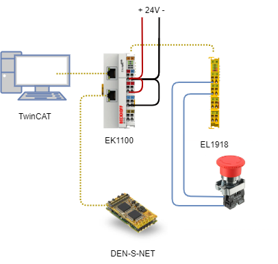
The example is using the following parts:
EtherCAT master: Computer with TwinCAT pre-installed
Safety drive: Novanta Safe Drive with a communication board
Safety master with safety inputs: EL1918
Basic Setup
The image of the drive above might differ to the one you have.
Video configuring STO
The video below is showing the configuration of the STO only.
The SS1 configuration is detailed in the Procedure below.
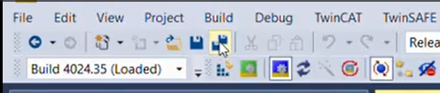
Be careful the first time you run TwinCAT XAE shell:
The TwinCAT Realtime Ethernet driver must be installed on the corresponding network adapter to enable connection to the Ethernet cards. To open a corresponding installation dialog, click in menu: TWINCAT > Show Realtime Ethernet Compatible Devices… in Application TcRteInstall > Yes. Search ethernet adapter > Install Ethernet TwinCAT Athernet Adapter.
The image and name of the Novanta drive in the video might differ to the one you are using.
Procedure to configure STO and SS1
Copy the ESI file of the DEN-S-NET in the device descriptors folder (C:\TwinCAT\3.1\Config\Io\EtherCAT).
Set up the basic project
Create a new TwinCAT XAE Project.
Scan the network (you can follow the procedure here: Connecting TwinCAT to Novanta EtherCAT Servo Drive
Check that all the devices are being identified. Please refer to the following Troubleshooting page if you cannot see the drive: TwinCAT shows "BOX" instead of "Drive"
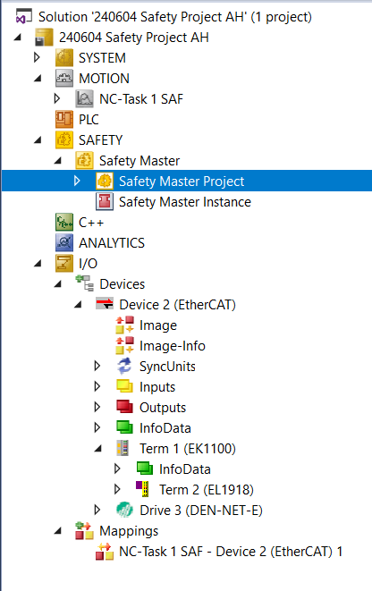
Configure the EL1918 module.
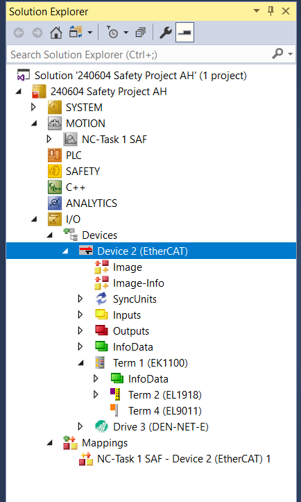
Navigate to I/O → Devices → Term 1 (EK1100) → Term 2 (EL1918).
Right click on Term 2 (EL1918) and Remove it.
Right click on Term 4 (EL9011) and Remove it.
Right click on Term 1 (EK1100) and press Add New Item.
Use the Search box to find EL1918. Click on Extended Information and Show Hidden Devices. Select EL1918, 8Ch, Safety Input 24V, TwinSAFE (EL1918-0000-0016).
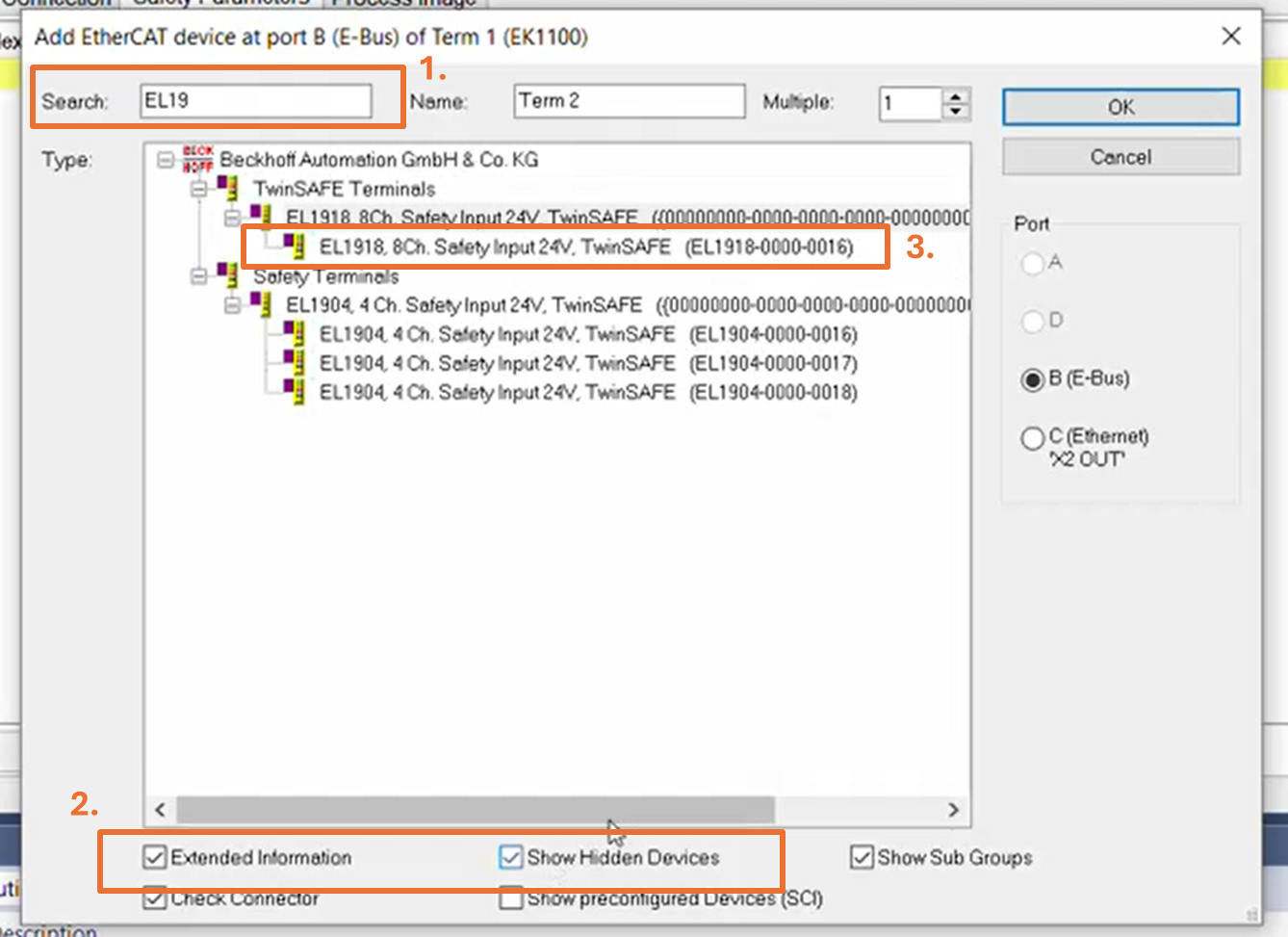
Press Save
Add the Safety Application project.
In the Solution Explorer, right-click the SAFETY block and select Add New Item.
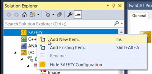
Choose TwinCAT Safety Project Preconfigured Inputs in the newly opened window. It is a good idea to rename it (i.e. “Safety Master”). Press Add.
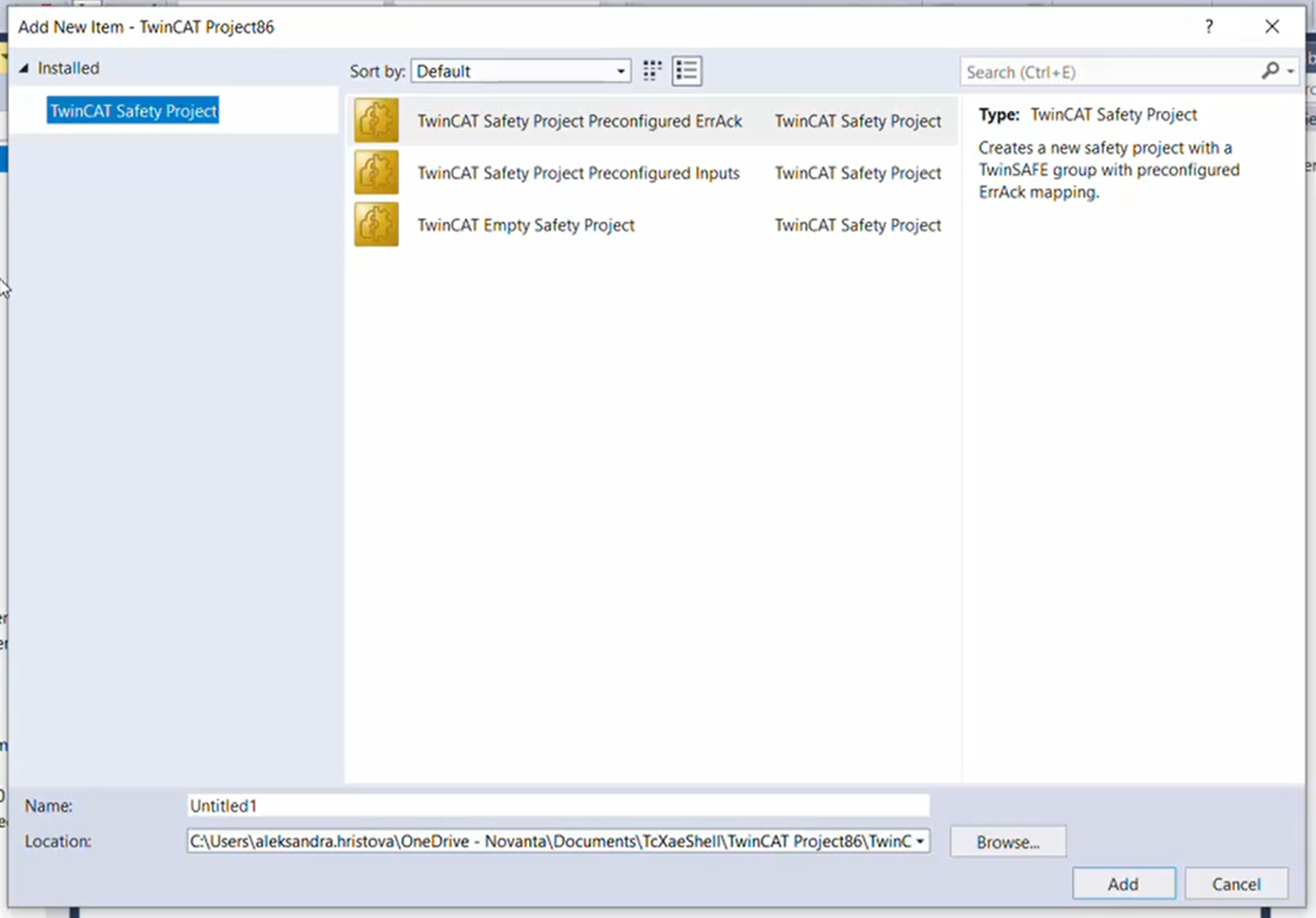
.
In the following window, select Hardware Safety PLC as Target System and press Ok.
Configure the safety master.
Right-click on Safety Master Project and select Properties.
In the Safety Master window, go to Target System and select EL1918 in the drop-down menu.
Click the icon next to the Physical Device field.
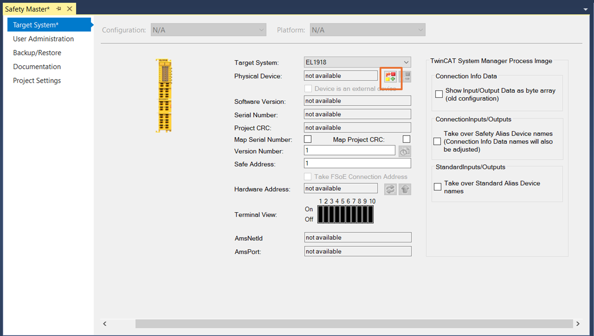
Choose EL1918 in the newly opened window and press OK. Data in Target System should now show the actual configuration of the device (software version, serial number…).
Press on the icons next to Hardware Address in the order presented in the graph below to copy them to the Safe Address.
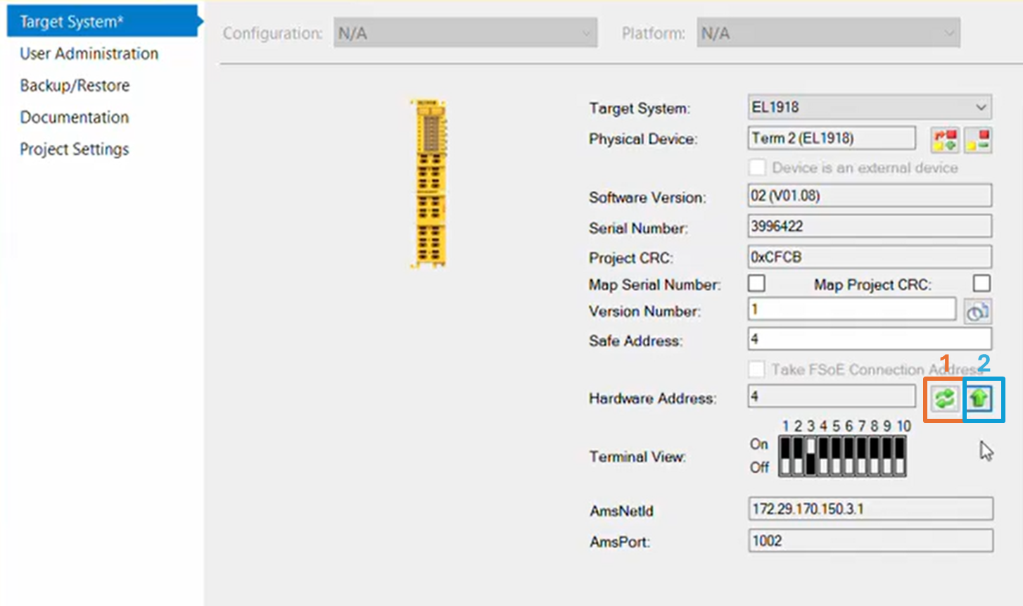
Press Save
Create two variables for running the project and error acknowledgement
In the solution explorer, right-click in SYSTEM/Tasks and select Add New Item.
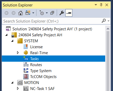
Insert a TwinCAT Task With Image.
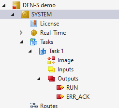
Right-click in the Outputs section of the newly created task and select Add New Item.
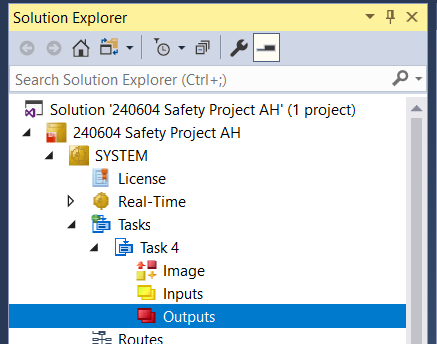
Select Insert a new variable. Change the name to RUN with type BIT and size 1 bit.
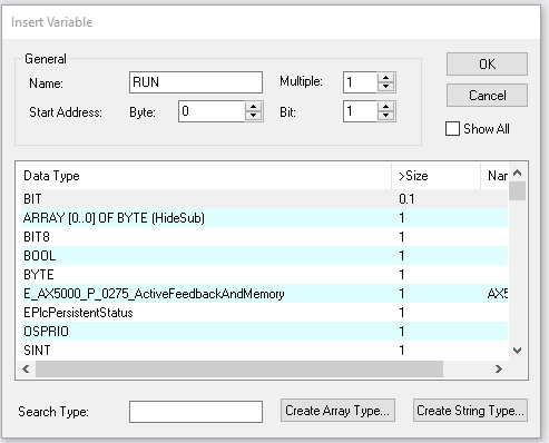
Create another variable with a name ERR_ACK with type BIT and size 1 bit.
Add the safety drive.
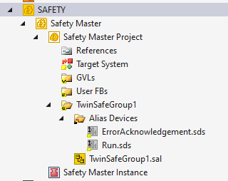
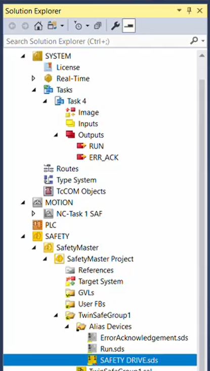
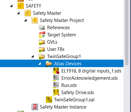
In the Solution Explorer, locate the Alias Devices subfolder inside Safety Master Project.
Right-click on the icon and select Add/New Item.
In the newly opened window, click on Safety/EtherCAT/Ingenia in the tree view menu, choose 0x00000010 - Safety drive (FSoE). It is a good idea to rename it (i.e. Safety Drive). Press Add.

Configure the safety drive.
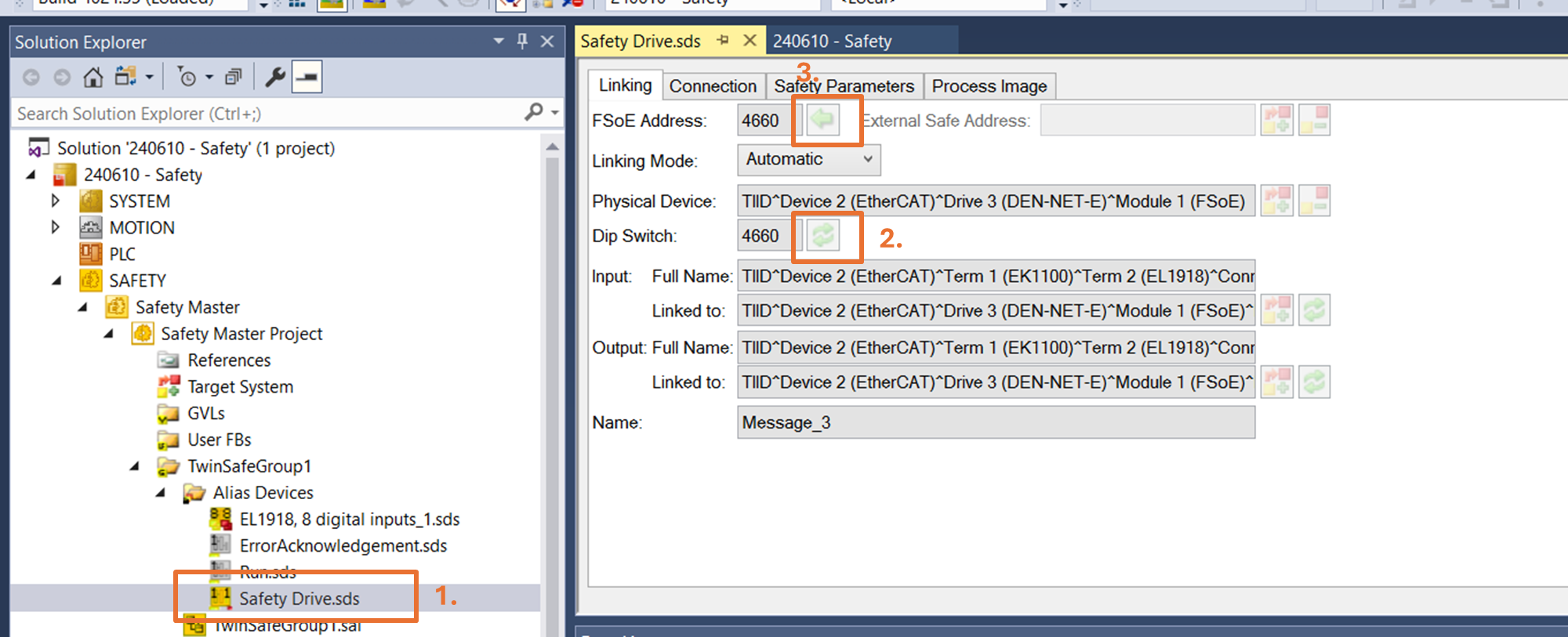
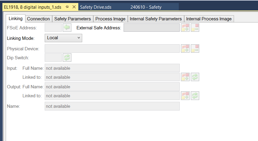
Double click on the newly created Safety Drive entry in the Solution Explorer.
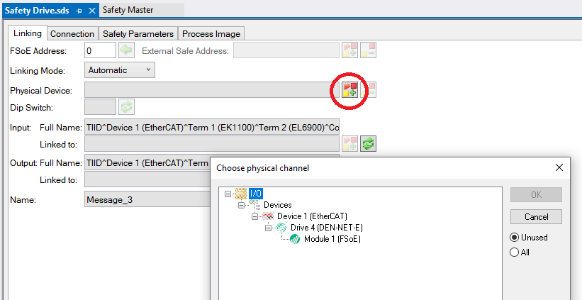
In the Safety Drive window, click the icon next to the Physical Device field.
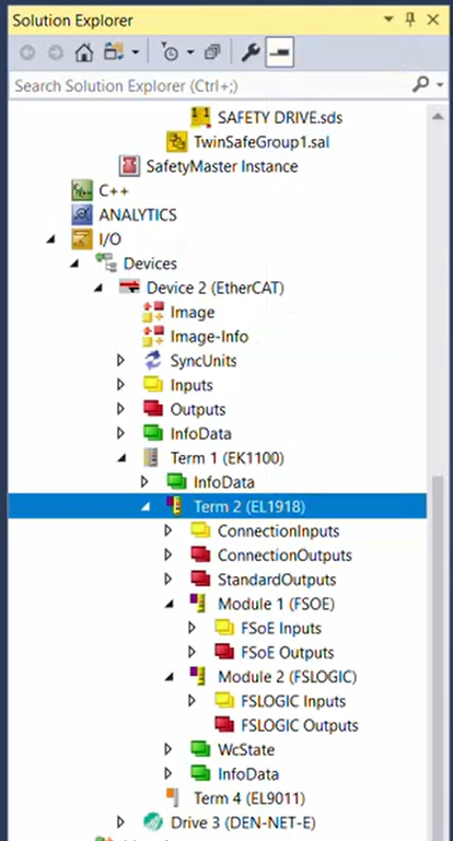
Choose Module 1 (FSoE) the newly opened window and press OK. The Inputs and outputs should appear now in the Linked to field (Note: The name of your drive might differ).
Press on the icons in the order below to make sure that the address is copied correctly.
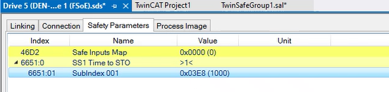
Open the Safety parameters. You will also notice that there is a register 0x6651 - SS1 Time to STO. Expand using the arrow to open the subindex and add the time (in ms) that you would like to use for enabling the STO.
Press on the Save button to auto-fill the linking parameters. It is normal if you get error messages.
Add and configure the safety inputs.
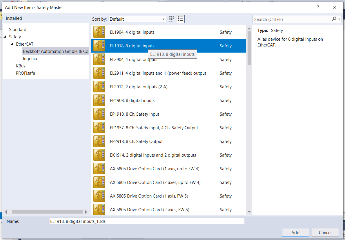
Repeat the same process in step 6a and 6b to add the safety inputs. Navigate to Safety/EtherCAT/Beckhoff Automation GmbH & Co. and add EL1918, 8 digital inputs.
Double click on the newly created EL1918, 8 digital inputs_1.sds device and change the Linking mode to Local.
Create the safety application.
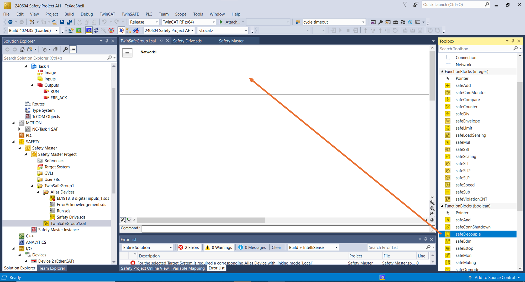
Double-click on TwinSafeGroup1.sal in the Solution Explorer.
In the newly opened window, drag a safeDecouple block from the Toolbox window into the top box of Network 1. If you cannot see the toolbox, you can add it from the View menu.
Right-click in the DecIn1 terminal of the safeDecouple block and select Add New Variable.
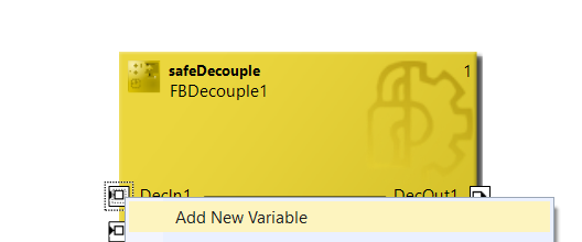
Name the new variable SafeInput.
Repeat for DecOut1 with a new variable named SafeOutput.
Link the safety application with actual inputs and outputs.
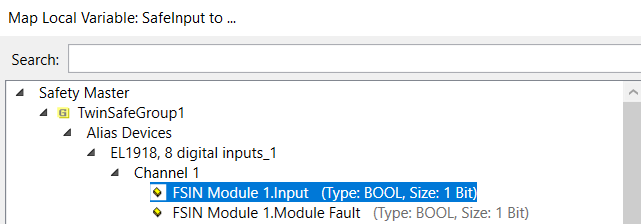
Go to the Variable mapping tab and click on the 3 dots for the Assignment of the SafeInput.
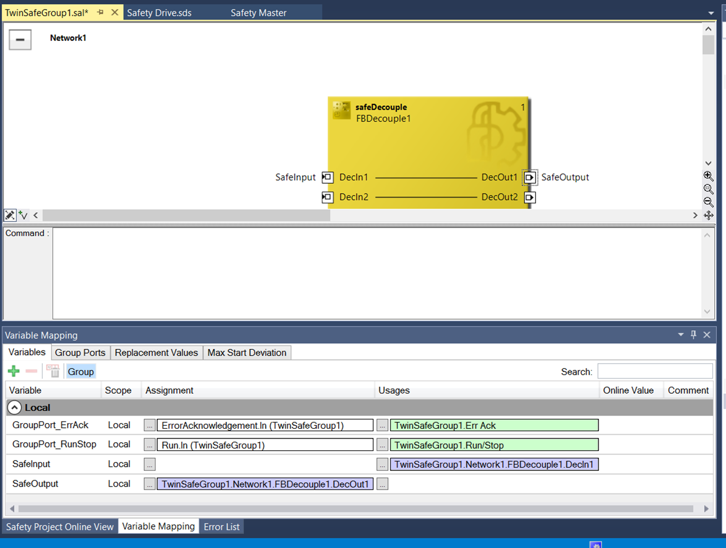
Choose the signal coming from the Channel 1 of the EL1918.
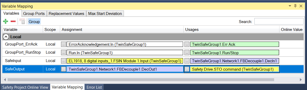
In the same area, click on the three dots for the Usages of the SafeOutput.
Choose as output for the SafeOutput the STO command of the Safety Drive.

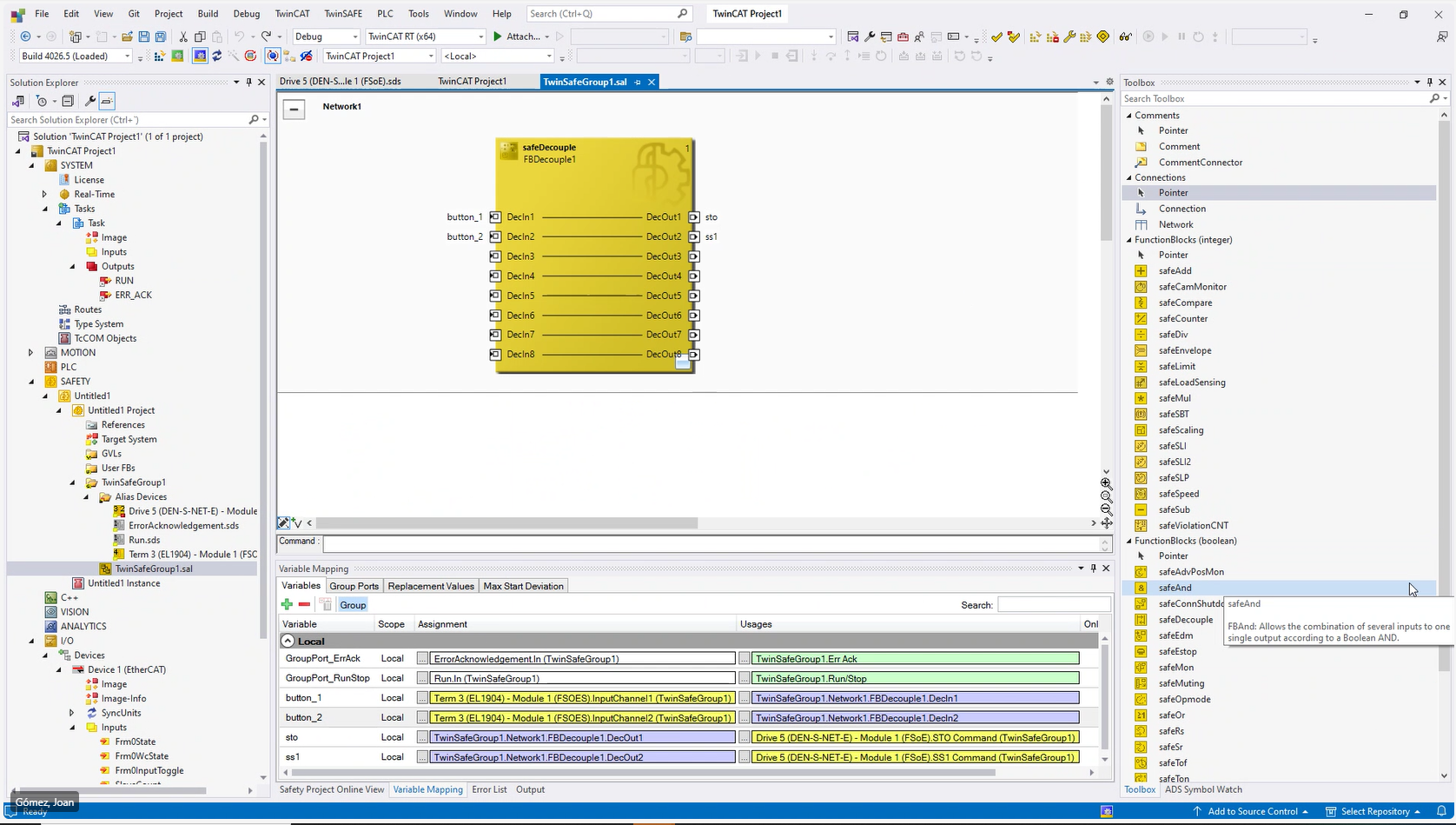
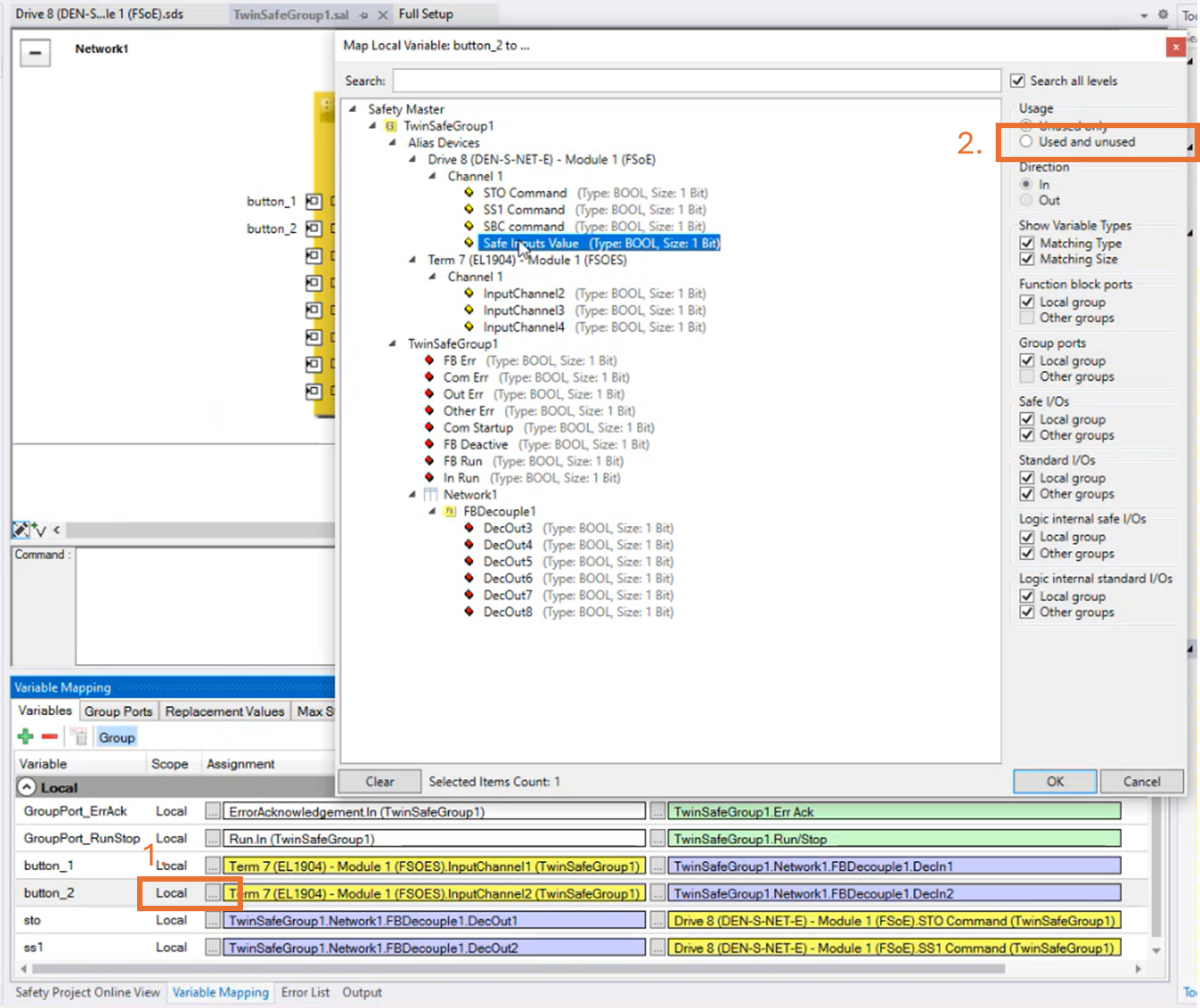
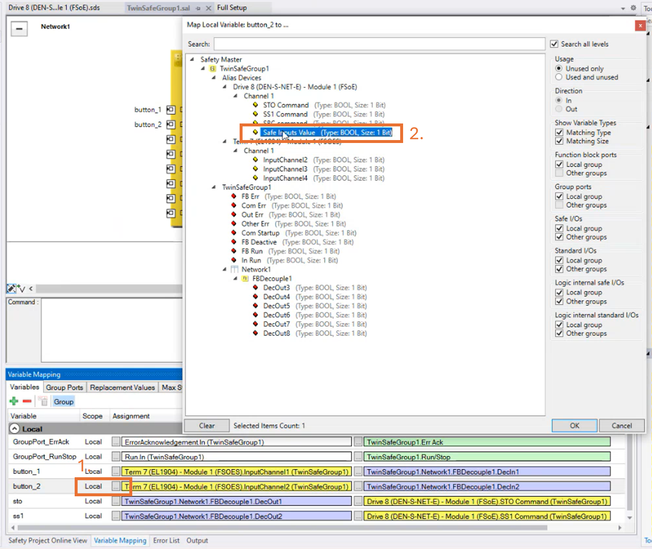
The same procedure is used to configure the SS1.
In the example below, the SS1 is configured to a second button, different to the STO one. The input selected is the Input Channel 2 and the output is FSOE SSI command.
Alternatively, one button can be connected to both STO and SS1. In order to do that, please select “Used and unused” in the Mapping window:
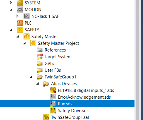
Link the RUN and ERR_ACK variables.
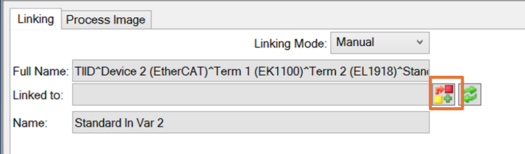
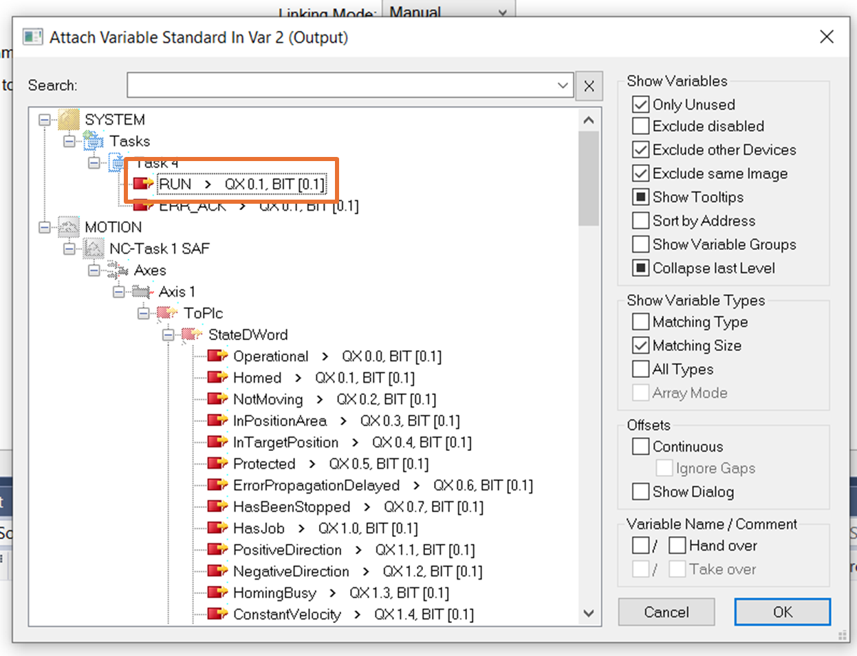
Double click in Run.sds in the Solution Explorer.
In the Linked to field, select the previously created RUN variable.
Repeat for ErrorAcknowledgement.sds with the ERR_ACK variable.
Press Save
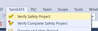
Validate the Safety Project.
Go to TwinSAFE/Verify Safety Project and check that no errors are being reported and a Verification Process successful message appears on the bottom of the window.
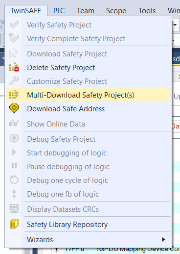
Download the Safety Project to the Safety Master
Go to TwinSAFE/Multi-Download Safety Project(s) and follow the steps of the guide.
The user is Administrator and the password TwinSAFE.
You will have to enter it twice.
Run the Safety Project.
Click on Activate configuration and accept to Restart in Run Mode.
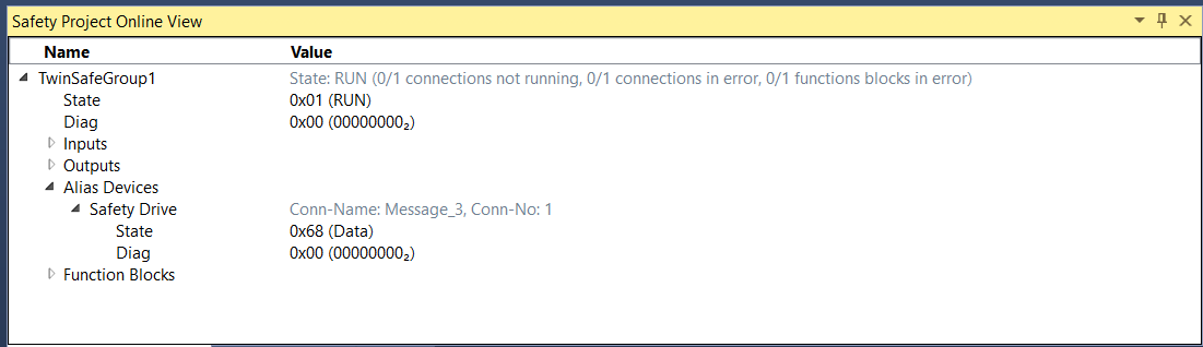
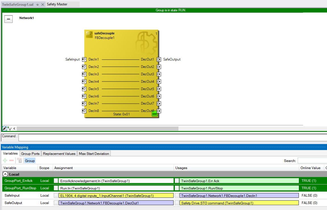
Select the view of the TwinSafeGroup1.sal and click TwinSAFE/Show Online Data.
The group should be in STOP state and the Safety Drive in Data state.
Enable the safe logic.
Right-click on the RUN variable and select Online Write “1”.
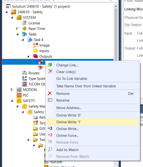
The group should be in RUN state and the Variable Mapping tab should show real-time data.
Check that the STO and the SS1 now responds to the pushbutton state.
Keep in mind that both STO and SS1 have to be released at the same time to allow movement.
Additional Features
Safe Input
The drive has implemented a physical input. This can be linked to an STO or SS1 instead of a pushbutton.
This feature also allows you to add data from another component to the safe system.
The mapping procedure is the same as above and the menu can be found within the mapping option of the decoupler:
Error Management
The following error registers have been implemented:
0x464D - Error Total Number - This register contains the number of errors in the queue. It resets at power up.
0x464E - Error List Index Request - This register is used to request an error code by its index on the error queue.
0x464F - Error List Requested Code - This register show the error code requested in the 0x464E register
Safe Input Mapping
Safe input of the drive can be used to link to a safety function. This allows the drive to execute the STO and SS1 safety requirements directly without going through the safety master. This is done through configuring the register 0x46D2 - Safe Inputs Map .
If a safety function (STO or SS1) is configured through the master and through the 0x46D2 register, it will have to be released from both sides. It is not sufficient to only release it from the drive or through the master.