Product Description
Capitan CORE is a high power, highly integrated, digital servo drive intended to be plugged or soldered to an application-specific daughter board. The drive features best-in-class energy efficiency thanks to its state of the art power stage, and can be easily configured with Ingenia's free software MotionLab 3.
Capitan CORE can be interfaced by means of its proprietary SPI-based Motion Control Bus protocol.
Main features:
Ultra-small footprint
48 VDC, 10 A continuous
Up to 99% efficiency
Up to 50 kHz current loop, 25 kHz servo loops
20 kHz ~ 200 kHz PWM frequency
16 bit ADC
Supports Halls, Quadrature encoder, SSI and Dual BiSS-C
Up to 4 simultaneous feedback sources
Full voltage, current and temperature protections
Typical applications:
Collaborative robot joints & end effectors
Robotic exoskeletons & wearable robots
Low power AGVs
UAVs
Industrial highly integrated servomotors
Smart motors
Battery-powered and e-Mobility
Low inductance motors
Lab equipment
Part numbering
Product | Ordering part number | Status | Image |
|---|---|---|---|
Capitan CORE Pluggable servo drive with communication through proprietary Motion Control Bus protocol. | CAP-CORE | PRODUCTION | 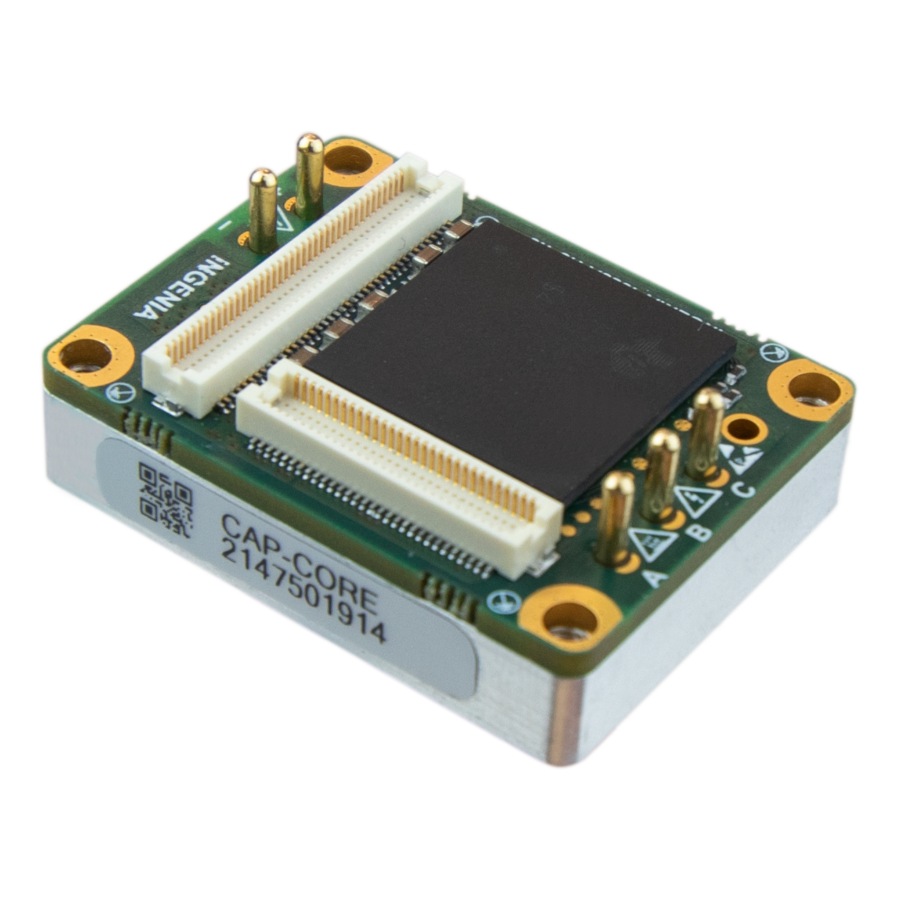 |
General Label Identification |
|---|
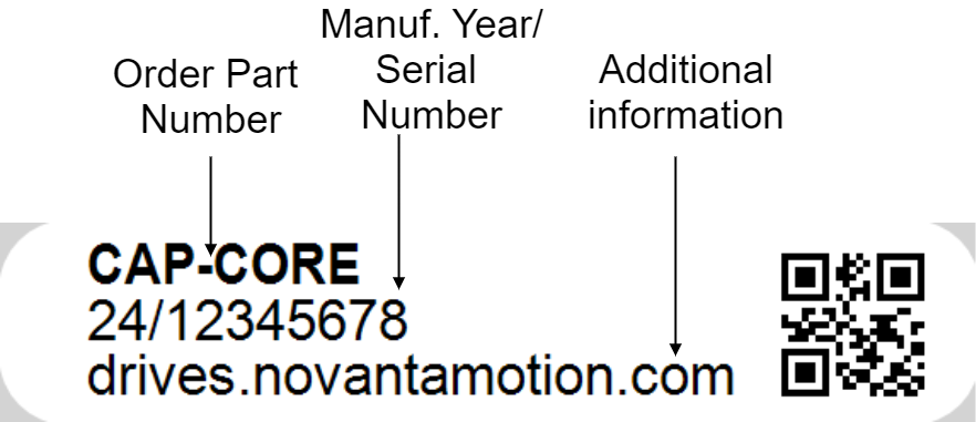 |
For applications requiring a pluggable drive enabled with EtherCAT or CANopen, please see Capitan NET.
For applications requiring a ready-to-go product, also enabled enabled with EtherCAT or CANopen, please see Capitan XCR.
Specifications
Electrical and Power Specifications
Minimum DC bus supply voltage | 5 VDC |
|---|---|
Maximum DC bus supply voltage | 60 VDC (continuous) |
Recommended power supply voltage range | 12 VDC ~ 48 VDC This voltage range ensures a safety margin including power supply tolerances and regulation during acceleration and braking. |
Internal drive DC bus capacitance | 17 µF Note that CAP-CORE uses ceramic capacitors. The capacitance value varies with DC bias and temperature. |
Logic supply voltage | 4.9 VDC ~ 5.1 VDC A minimum of 500 mA should be provided. Higher current may be needed depending on the feedbacks used. Rise time of the 5 V supply must be < 5 ms |
Boot-up time | 0.6 s |
Minimum shutdown time | 500 ms |
Maximum continuous phase current | 10 A Typically, 10 A can be obtained working at 48 V, 50 kHz with an appropriate cooling to keep case temperature under 85 ºC. On higher temperatures an automatic current derating will be applied to protect the system. See Thermal and Power Specifications below. For disambiguation on current definitions please see Disambiguation on current values and naming for Ingenia Drives. |
Maximum peak phase current | 20 A @ 1 sec Notice that peak current could be limited by an automatic current derating algorithm. In order to get 20 A, case temperature should be kept below 60 ºC. |
Maximum continuous switch-off rectified current |
Notice that maximum current is dependent on temperature and heatsink attached. At higher temperature, the lower the current. For more information about heatsink applied, see Thermal and Power Specifications below. A continuous use of disabled power stage as rectifier is not recommended for thermal limitations. |
Maximum continuous output power | > 500 W How the output power is calculated in an Ingenia drive. |
Efficiency | Up to 99% |
Maximum DC Bus voltage utilization | 99.5% @ 20 kHz 98.9% @ 50 kHz 97.95% @ 100 kHz 96% @ 200 kHz Note 1: these values assume a Sinusoidal commutation and no load connected. |
Standby logic supply consumption | ~ 1 W typ. See details and conditions in the section below. |
Motion Control Specifications
Supported motor types |
|
|---|---|
Power stage PWM frequency (configurable) | 20 kHz, 50 kHz (default), 100 kHz, 200 kHz |
Current sensing | 3 phase, shunt-based current sensing. 16 bit ADC resolution. Accuracy is ±2% full scale |
Current sense resolution | 1.007 mA/counts |
Current sense range | ± 33 A |
Max. Current loop frequency (configurable) | 50 kHz Check the Power Stage & Control loops relationship section below. |
Max. servo loops frequency (position, velocity & commutation) (configurable) | 25 kHz Check the Power Stage & Control loops relationship section below. |
Feedbacks |
All feedback inputs are single-ended, 3.3 V logic levels. *Not all the existing absolute encoders are supported. Contact Ingenia for further information. |
Supported target sources |
*MCBus is a SPI-based proprietary protocol for Ingenia CORE drives. |
Control modes |
|
Inputs/Outputs and Protections
General purpose Inputs and outputs | 4x non-isolated single-ended digital inputs - 3.3 V logic level. Can be configured as:
4x non-isolated single-ended digital outputs - 3.3 V logic level, 3 mA max. sink / source current. Can be configured as:
2x ±3.3 V ,16-bit, differential analog inputs for load cells or torque sensors. Can be read by the Master to close a torque loop. |
|---|---|
Shunt braking resistor output | Configurable over any of the digital outputs (see above). Enabling this function would require an external transistor or power driver. |
Motor brake output | Dedicated, PWM-capable, 3.3 V digital output for driving a mechanical brake. Turn-on and turn-off times are configurable. Enabling this function would require an external transistor or power driver. |
Safe Torque OFF inputs | 2x dedicated, non-isolated STO digital inputs (3.3 V and 5 V tolerant). |
Motor temperature input | 1x dedicated, 5 V, 12-bit, single-ended analog input for measuring motor temperature. NTC, PTC, RTD, linear voltage sensors , silicon-based sensors and thermal switches are supported. |
Protections |
|
Communication for Operation
MCB | Proprietary Motion Control Bus protocol based on SPI. |
|---|
Environmental Conditions
Environmental test methods | IEC 60068-2 |
|---|---|
Case temperature (Operating) | -20 ºC to +85 ºC Check the Current Derating section below. |
Case temperature (Non-Operating) | -40 ºC to +100 ºC |
Thermal Shock (Operating) | 25 ºC to 60 ºC in 25 min |
Maximum Humidity (Operating) | up to 95%, non-condensing at 85 ºC |
Maximum Humidity (Non-Operating) | up to 95%, non-condensing at 85 ºC |
Altitude (Operating) | -400 m to 2000 m |
Vibration (Operating) | 5 Hz to 500 Hz, 4-5 g |
Mechanical Shock (Operating) | ±15g Half-sine 11 msec |
Mechanical Shock (Non-Operating) | ±15g Half-sine 11 msec |
Reliability Specifications
MTBF | > 650.000 h Based on FIDES method for Standard Life Profile at 40 °C average. Other scenarios available on demand. |
|---|---|
Isolation between aluminum case (PE) and live circuits | Basic insulation according to IEC 61800-5-1. > 200 MΩ. Measured between PE (case) and GND_P and +SUP and phases. Note: The drive includes 2 nF EMC capacitance between the power supply negative (GND_P) and the enclosure (PE). |
Mechanical Specifications
Aluminum case | Yes (connectors side open). Minimum wall thickness > 0.75 mm. |
|---|---|
Horizontal dimensions | 34.5 mm x 26 mm |
Height | 10.30 mm (including Mezzanine connector) 14.59 mm (including full length of the power pins) |
Weight | 17.5 gr |
Compliance
EC Directives | CE Marking
|
|---|---|
Electromagnetic Compatibility (EMC) Standards |
|
Product Safety Standards |
|
Functional Safety Standards | Safe Torque Off (STO)
See Safety Manual - Safe Torque Off (STO) section for mandatory Integration Requirements. |
Environmental Test methods | IEC 60068-2:
|
Product Revisions
Revision | Date | Notes |
|---|---|---|
1 |
| Initial version |
D |
| Current version |
Thermal and Power Specifications
Standby power consumption
The following table shows the standby power consumption when the Capitan power stage is disabled, no feedbacks or I/Os are connected. At this point the power consumption comes from the 5 V supply input only. The table also shows the "active standby" dc bus power consumption when the power stage is enabled, motor current is set to 0 and housing temperature is kept at 50 ºC.
Power supply voltage | Standby 5 V logic supply consumption | Power consumption switching at 0 current | |||
|---|---|---|---|---|---|
20 kHz | 50 kHz | 100 kHz | 200 kHz | ||
12 V | 1.03 W | 0.02 W | 0.04 W | 0.07 W | 0.14 W |
24 V | 0.05 W | 0.12 W | 0.22 W | 0.44 W | |
48 V | 0.16 W | 0.37 W | 0.68 W | 1.31 W | |
60 V | 0.23 W | 0.52 W | 0.98 W | 1.91 W | |
Thermal model
The Capitan Core is designed to be mounted on a cooling plate or heatsink to achieve its maximum ratings. In order to calculate the heatsink requirements, the power dissipation can be estimated below.
In some low power applications, the Capitan is NOT required to be mounted to any heatsink. In this case its thermal resistance from housing/case to ambient Rth(h-a) can be estimated between 8 K/W, to 12 K/W assuming 10 cm clearance to allow air convection at sea level. A good thermal design of the PCB providing big thermal ground planes on the contact areas can greatly increase the heat dissipation and reduce Rth(h-a) significantly.
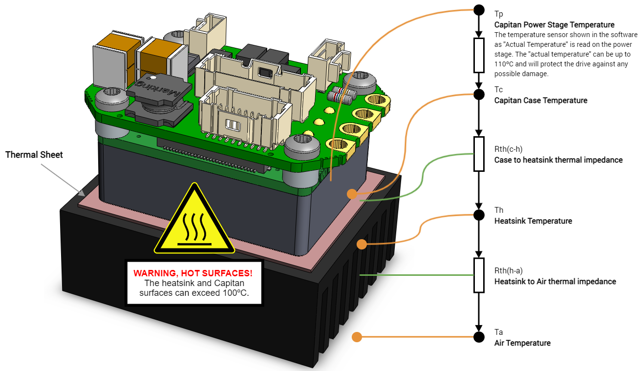
*Product shown differ from Capitan CORE.
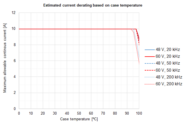
Current derating
The following figure show the maximum motor phase current at different case temperatures and operating points. The graph expresses the achievable current including the derating algorithm that limits the current based operation conditions and the power stage temperature.
Notice that current is expressed in crest value for a 3 phase BLAC motor. For further clarifications and conversion to equivalent RMS values please refer to Disambiguation on current values and naming for Ingenia Drives.
To ensure a proper performance of Capitan XCR, the case temperature should be held always below 85 ºC (Tc-max = 85 ºC).
Heat dissipation and heatsink calculation
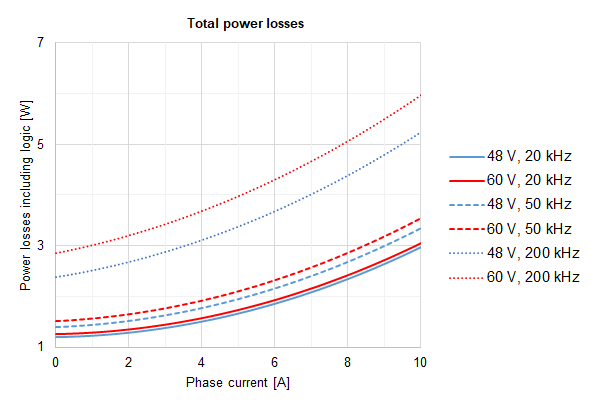
Following figure show the total power losses at different operating points. This includes logic supply which is an important contributor at low loads. As can be seen, lower PWM frequency and voltage leads to lower power losses.
Please, use the following procedure to determine the required heatsink:
Based on the voltage & continuous (averaged) current required by your application and Current derating graph determine the Case temperature Tc. Remember that Case temperature must be always below 85 ºC (Tc < 85 ºC)
For example: If the application requires 10 A @ 60 V (20 kHz) the Tc will be 85 ºC
Based on the voltage & continuous current required by your application and Power losses graph determine the generated Power Losses PL to be dissipated.
For example: If the application requires 10 A @ 60 V (20 kHz) the PL will be 3.06 W
Determine the Thermal impedance of the used thermal sheet Rth(c-h)
For example, a thermal sheet TGX-150-150-0.5-0, which has an estimated thermal impedance of Rth(c-h) = 0.2 K/W
Based on the ambient temperature and using the following formula determine the maximum thermal impedance to air of the required heatsink Rth(h-a)
We don't have a way to export this macro.For example: If the application requires 10 A @ 60 V (20 kHz) working at Ta = 25 ºC and we use a thermal sheet with Rth(c-h) = 0.2 K/W the required thermal impedance of the heatsink will be Rth(h-a) = 12.8 K/W
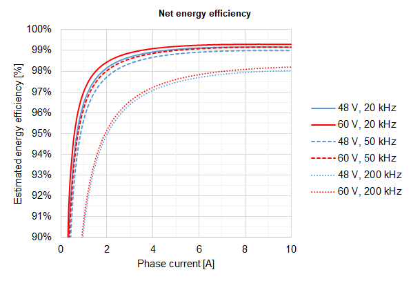
Energy efficiency
The following graph shows the net energy efficiency including logic for various operation points assuming 50ºC case temperature and maximum output power. Very high efficiencies > 99% can be achieved at 20 kHz PWM frequency.
Power Stage & Control loops relationship
The power stage PWM frequency can be adjusted in 4 different frequencies. Each frequency has an associated rate for the control loops, as specified in the following table.
Power stage PWM frequency | Current loop frequency | Servo loops frequency (position, velocity, commutation & shunt) |
|---|---|---|
20 kHz | 20 kHz | 20 kHz |
50 kHz | 50 kHz | 25 kHz |
100 kHz | 50 kHz | 25 kHz |
200 kHz | 50 kHz | 25 kHz |