Product Description
Denali XCR is a mid-power, highly integrated, ready-to-use digital servo drive. The drive includes all the required interface electronics and connectors, features best-in-class energy efficiency thanks to its state-of-the-art power stage, and can be easily configured with free software MotionLab 3.
Denali XCR is enabled with EtherCAT or CANopen communications.
Main features:
Ultra-small footprint
48 VDC, 5 A continuous
Up to 50 kHz current loop, 25 kHz servo loops
20 kHz ~ 200 kHz PWM frequency
16 bit ADC current sensing
Supports Halls, Quadrature encoder, SSI, and Dual BiSS-C
Up to 4 simultaneous feedback sources
Full voltage, current and temperature protections
Safety Torque Off (STO SIL3 Ple) inputs
Typical applications:
Collaborative robot joints & end effectors
Robotic exoskeletons & wearable robots
Medical applications
UAVs
Lab equipment
Low inductance motors
Part Numbering
Product | Ordering part number | Status | Image |
|---|---|---|---|
Denali XCR EtherCAT Ready-to-use servo drive featuring EtherCAT communications. | DEN-XCR-E | PRODUCTION | 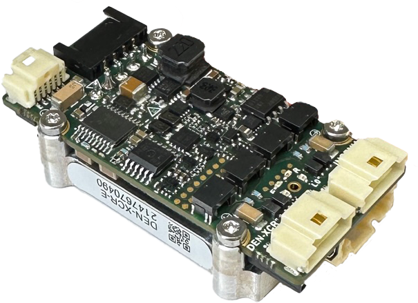 |
Denali XCR CANopen Ready-to-use servo drive featuring CANopen. | DEN-XCR-C | PRODUCTION |
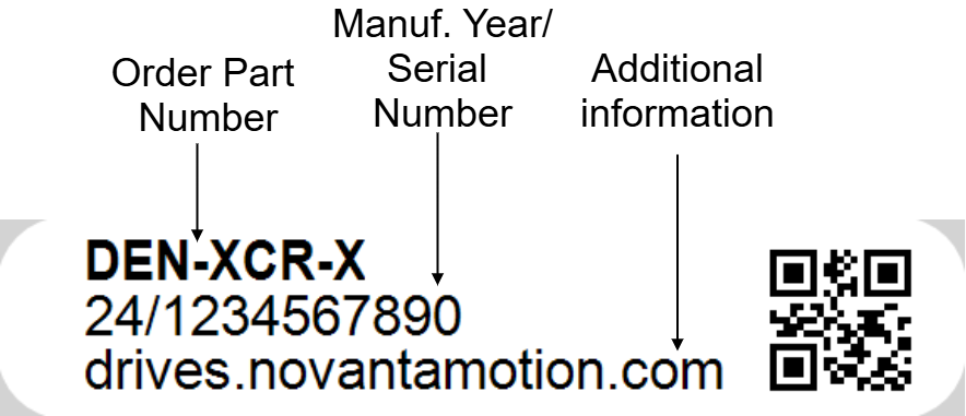
General Label Identification |
|---|
 |
For applications requiring a pluggable drive enabled with EtherCAT or CANopen, please see Denali NET.
For applications not requiring CANopen or EtherCAT, please contact us for Denali CORE
Specifications
Electrical and Power Specifications
Minimum absolute power supply voltage | 7 VDC |
|---|---|
Maximum absolute power supply voltage | 60 VDC |
Recommended power supply voltage | 8 VDC ~ 48 VDC This voltage range ensures a safety margin including power supply tolerances and regulation during acceleration and braking. |
Internal drive DC bus capacitance | 19.7 µF Note that DEN-XCR uses ceramic capacitors. The capacitance value varies with DC bias and temperature. |
Boot-up time | 4 s |
Minimum shutdown time | 500 ms |
Maximum continuous phase current | 5 A 5 A can be obtained working at 48 V with an appropriate dissipation to keep the product plate under 85 ºC. On higher temperatures an automatic current derating will be applied to protect the system. See Thermal and Power Specifications below and Installation for further details. For disambiguation on current definitions please see Disambiguation on current values and naming for Ingenia Drives. |
Maximum peak phase current | 10 A @ 1 sec Notice that peak current could be limited by an automatic current derating algorithm. |
Maximum continuous output power | > 250 W How the output power is calculated. |
Efficiency | Up to 98% |
Maximum DC Bus voltage utilization | 99.3% @ 20 kHz 98.5% @ 50 kHz 92.5% @ 100 kHz 78.1% @ 200 kHz Note 1: these values assume a Sinusoidal commutation and no load connected. |
Standby logic supply consumption |
See details and conditions in the Thermal and Power Specifications below. |
Motion Control Specifications
Supported motor types |
|
|---|---|
Power stage PWM frequency (configurable) | 20 kHz, 50 kHz (default), 100 kHz, 200 kHz |
Current sensing | 3 phase, shunt-based current sensing. 16 bit ADC resolution. Accuracy is ±2% full scale. |
Current sense resolution | 0.505 mA/counts |
Current sense range | ± 16.5 Apk (full range) |
Maximum Current loop frequency | 50 kHz Check the Power Stage & Control loops relationship section below. |
Maximum servo loops frequency (position, velocity & commutation) | 25 kHz Check the Power Stage & Control loops relationship section below. |
Feedbacks |
Not all the existing absolute encoders are supported. Please consult the Feedbacks section. |
Supported target sources | Network communication (EtherCAT / CANopen) |
Control modes |
|
Inputs/Outputs and Protections
General purpose inputs and outputs | 2x non-isolated single-ended digital inputs - 3.3 V logic level & 5 V compatible. Can be configured as:
2x non-isolated single-ended digital outputs - 3.3 V logic level, short-circuit protected. Can be configured as:
2x ±11 V ,16-bit, differential analog inputs for load cells or torque sensors. Can be read by the Master to close a torque loop. 1x 0.3 V - 3 V buffered analog output:
Find more detailed information in the Inputs and Outputs page. |
|---|---|
Shunt braking resistor output | Configurable over any of the general purpose digital outputs (see above). Enabling this function requires an external transistor or power driver. |
Safe Torque OFF inputs | 2x Dedicated, isolated (> 4 GΩ, 1 kV) STO input. 24 V Industrial Logic level. Active-low.
Details: Safe Torque Off (STO). |
Motor temperature input | 1x dedicated, 3.3 V, 12-bit, single-ended analog input for motor temperature (1.65 kΩ pull-up to 3.3 V included). NTC, PTC, RTD, linear voltage sensors , silicon-based sensors and thermal switches are supported. Find more detailed information in the Motor Temperature and Brake page. |
Motor brake output | 1 A, 48 V (60 V absolute maximum), dedicated brake output. Open drain with re-circulation diode. Brake enable and disable timing can be configured accurately. PWM modulation available to reduce brake activation/holding voltage and power consumption. It includes a current sense analog output to monitor the brake current, which at the same time can be routed to an analog input to control the brake. |
Protections |
|
Communication for Operation
EtherCAT (DEN-XCR-E) | CANopen over EtherCAT (CoE) File over EtherCAT (FoE) Ethernet over EtherCAT (EoE) |
|---|---|
CANopen (DEN-XCR-C) | CiA-301, CiA-303, CiA-305, CiA-306 and CiA-402 (4.0) compliant. 125 kbps to 1 Mbps (default). Non-isolated. Termination resistor not included. |
Environmental Conditions
Environmental test methods | IEC 60068-2 |
|---|---|
Case temperature (Operating) | -20 ºC to +55ºC Check the Current Derating section below. |
Case temperature (Non-Operating) | -40 ºC to +100 ºC |
Maximum Humidity (Operating) | up to 93%, non-condensing at 60ºC |
Maximum Humidity (Non-Operating) | up to 93%, non-condensing at 60ºC |
Altitude (Operating) | -400 m to 2000 m |
Vibration (Operating) | 10 Hz to 150 Hz, 1 g |
Mechanical Shock (Operating) | ±5g Half-sine 30 msec |
Mechanical Shock (Non-Operating) | ±5g Half-sine 30 msec |
Mechanical Specifications
Dimensions | 49.8 mm x 26.50 mm x 14.73 mm |
|---|---|
Weight | 25.6 g |
Compliance
EC Directives | CE Marking
|
|---|---|
Electromagnetic Compatibility (EMC) Standards |
|
Product Safety Standard |
|
Functional Safety Standard | Safe Torque Off (STO) - Certification pending (rev F)
See Safe Torque Off (STO) section for mandatory Integration Requirements. This section has been updated through the different product revisions. Take a look to the PCN section. |
Environmental Test methods | IEC 60068-2:
|
Product Revisions
Please see: Part Change Notification
Thermal and Power Specification
Standby power consumption
The following table shows the estimated standby power consumption when the Denali power stage is enabled.
Power supply voltage | Power stage disabled | Power stage enabled and switching at 0 current (EtherCAT with 2 ports active) | ||||
|---|---|---|---|---|---|---|
EtherCAT (2 ports active) | CANopen | 20 kHz | 50 kHz | 100 kHz | 200 kHz | |
7 V | 2.05 W | 1.74 W | 2.05 W | 2.07 W | 2.08 W | 2.11 W |
24 V | 2.28 W | 1.84 W | 2.33 W | 2.40 W | 2.50 W | 2.72 W |
48 V | 2.47 W | 2.05 W | 2.63 W | 2.83 W | 3.16 W | 3.82 W |
Considered environment
No feedbacks connected
No I/Os connected
Motor current is set to 0 (Voltage mode 0 V)
STO circuitry supplied at 5 V (consumption considered).
Thermal model
The Denali XCR is designed to be mounted on a cooling plate or heatsink to achieve its maximum ratings.
Current derating
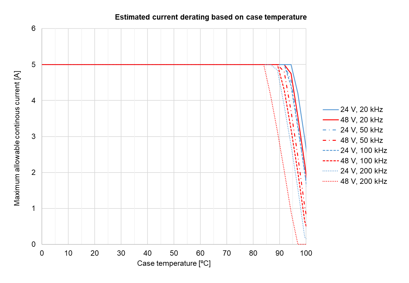
The figure below shows the maximum motor phase current at different case temperatures and operating points. Results are referenced to the case temperature, providing a known interface for any system. The graph expresses the achievable current including the derating algorithm that limits the current-based operation conditions and the power stage temperature.
Notice that current is expressed in crest value for a 3-phase BLAC motor, not RMS. For further clarifications and conversion to equivalent RMS values please refer to Disambiguation on current values and naming for Ingenia Drives.
To ensure the proper performance of Denali XCR, the case temperature should always be held below 55 ºC (Tc-max = 55 ºC).
Heat dissipation and heatsink calculation
The following figure shows the estimated total power losses at different operating points. As can be seen, lower PWM frequency and voltage lead to lower power losses.
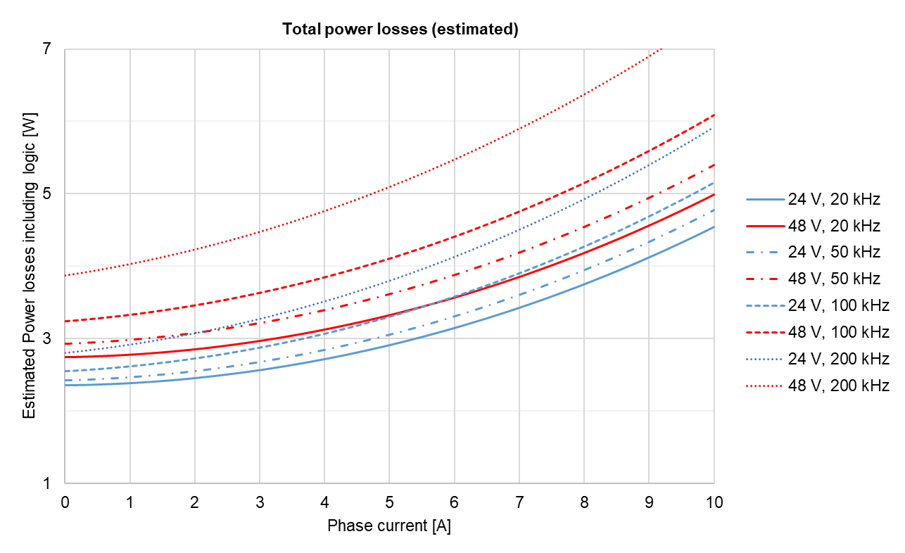
Please, use the following procedure to determine the required heatsink:
Based on the voltage & continuous (averaged) current required by your application and Current derating graph determine the Case temperature Tc. Remember that Case temperature must be always below 85 ºC (Tc < 85 ºC)
For example: If the application requires 3 A @ 48 V (200 kHz) the Tc maximum could be 90 ºC. Since this is above 85ºC the Tc should be limited to 85ºC.
Based on the voltage & continuous current required by your application and Power losses graph determine the generated Power Losses PL to be dissipated.
For example: If the application requires 3 A @ 48 V (200 kHz) the PL will be 4.75 W
Determine the Thermal impedance of the used thermal sheet Rth(c-h)
For example, a thermal sheet TGX-150-150-0.5-0, which has an estimated thermal impedance of Rth(c-h) = 0.2 K/W
Based on the ambient temperature and using the following formula determine the maximum thermal impedance to air of the required heatsink Rth(h-a)
a. For example: If the application requires 3 A @ 48 V (200 kHz) working at Ta = 25 ºC and we use a thermal sheet with Rth(c-h) = 0.2 K/W the required thermal impedance of the heatsink will be Rth(h-a) ≤ 13.53K/W.
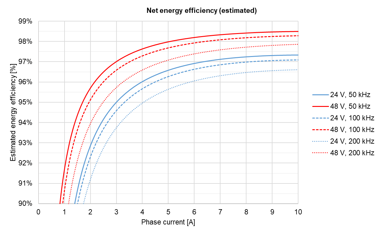
Energy efficiency
The following graph shows the estimated electrical energy efficiency including logic for various operation points assuming 50 ºC case temperature and the drive delivering the maximum output power (i.e. maximum output voltage and motor speed). As seen, very high efficiencies > 95% can be expected at all PWM frequencies.
Power Stage & Control loops relationship
The power stage PWM frequency can be adjusted in 4 different frequencies. Each frequency has an associated rate for the control loops, as specified in the following table.
Power stage PWM frequency | Current loop frequency | Servo loops frequency (position, velocity, commutation & shunt) |
|---|---|---|
20 kHz | 20 kHz | 20 kHz |
50 kHz | 50 kHz | 25 kHz |
100 kHz | 50 kHz | 25 kHz |
200 kHz | 50 kHz | 25 kHz |