Interpolated position mode
The interpolated position mode is used to control multiple coordinated axes or a single axis with the need for time-interpolation of set-point data. The interpolated position mode normally uses time synchronization mechanisms for a time coordination of the related drive units.
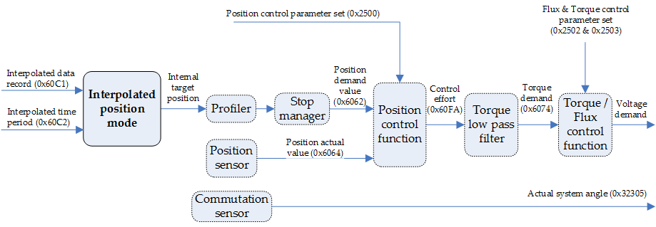
The interpolated position is delivered to the profiler, which using the interpolation time preset by the user, continuously generates the values for the desired position (see Profiler in interpolated position mode). This position is used by the position control function (See 0x2500 - Position control parameters set).
An overall structure of the interpolated position mode is presented in next Figure:
In this mode, the master must specify the starting point and update it at constant time intervals, as indicates the following figure.
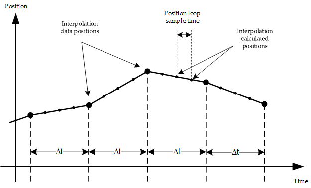
In each interpolation cycle (or each update time of the position loop), emcl calculates the position demanded by means of the positions given by the master. The type of interpolation available at the moment in emcl is linear, thus, the demanded speed is calculated by means of the difference between desired actual position and the previous one.
The limiting functions of speed, acceleration and deceleration are not applied in this mode, so the master must take into consideration these parameters during the elaboration of the set of data.
emcl has an input buffer of 16 positions, implemented like a FIFO that allows reducing the needs of real time transmission of the system. Thus, the master can transmit a data set initially and then just maintain a cadence of messages approximated to the period of interpolation.
Interpolated position mode does not work with AC induction motors.
Synchronization between axis
Interpolated position mode allows for synchronizing the movement between multiple axes. The movements of different axes will be solely synchronous if all the axes are in interpolated position mode and the interpolation is activated simultaneously.
In order to realize this movement, the master must map the controlword of the device in a synchronous RPDO and later to use the controlword to activate the interpolation of all the axes. Nothing will happen until the following message of SYNC is generated. Then, all the devices would activate the interpolation simultaneously and will begin to realize movements.
The interpolated position mode is controlled using controlword and statusword. The following figure shows the internal states of this mode, only valid in Operation Enable state.
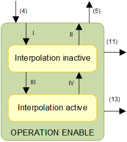
- Interpolation inactive: To enable this state the system must be in Operation Enable with interpolated position mode selected and enabled interpolation bit at zero (it should be done by means of controlword). The drive device will accept input data and will buffer it for interpolation calculations, but it will not move the axis.
Interpolation active: To enable this state the system must be in Operation Enable with interpolated position mode selected and enabled interpolation bit at one (it should be done by means of controlword). The drive unit will accept input data and it will move the axis.
Transition
Event
Action
I
Interpolated mode selected (object 0x6060)
None
II
Interpolated mode not selected (object 0x6060)
None
III
Enable interpolation (bit 4 of controlword is 1)
None
IV
Disable interpolation (bit 4 of controlword is 0)
None
Controlword
The binary representation of the register value and its corresponding meaning are as follows:
Bit number: | 15 | … | 9 | 8 | 7 | 6 | 5 | 4 | 3 | … | 0 |
|---|---|---|---|---|---|---|---|---|---|---|---|
| - | Halt | - | - | reserved | Enable interpolation | - | ||||
The action taken is described below, depending on the value of each bit:
Name | Value | Description |
|---|---|---|
Enable interpolation
| 0 | Disable interpolation |
1 | Enable interpolation | |
Halt | 0 | Execute positioning |
1 | Stop axis with profile deceleration (if not supported with profile acceleration) |
Statusword
The binary representation of the register value and its corresponding meaning are as follows:
Bit number: | 15 | 14 | 13 | 12 | 11 | 10 | 9 | … | 0 |
|---|---|---|---|---|---|---|---|---|---|
| - | - | Ip mode active | - | Target reached | - | |||
The meaning of each bit is described below, depending on its value:
Name | Value | Description |
|---|---|---|
Target reached
| 0 | Halt = 0: Target position not reached |
1 | Halt = 0: Target position reached | |
Ip mode active
| 0 | Interpolation inactive |
1 | Interpolation active |
Related objects
0x60C1 - Interpolation data record
0x60C2 - Interpolation time period
0x60C4 - Interpolation data configuration
0x2500 - Position control parameters set