Command sources
The target or command sources are used for setting a reference for position, velocity or torque controllers. Jupiter Servo Drive supports the following command sources:
- Network communication interface (USB, CANOpen, RS-485 or EtherCAT)
- Standalone
- Analog input (±10 V or 0 V to 5 V)
- Step and direction
- PWM command (single and dual input mode)
- Encoder follower / electronic gearing.
Analog inputs, step and direction, PWM command and encoder follower / electronic gearing are interfaced through general purpose inputs. Next table illustrates which variables can be controlled with each command source:
Command source | Target variable |
|---|---|
Network interface | Position, velocity, torque |
Standalone | Position, velocity, torque |
| Analog input (+/- 10 V o 0 – 5 V) | Position, velocity, torque |
Step and direction | Position |
| PWM command | Position, velocity, torque |
Encoder following / electronic gearing | Position |
Please, see Command sources section from E-Core documentation for configuration details.
Network communication interface
Jupiter Servo Drive can utilize network communication as a form of input command. Supported network interfaces for Jupiter Servo drive are CAN (CANopen protocol), USB, RS-485 (or RS232) and EtherCAT.
USB and RS232 interfaces are not suitable for long distances or noisy environments. These protocols are only recommended for configuration purposes.
For normal operation, it is suggested to use CAN, RS-485 or EtherCAT. These interfaces are more robust against noise than USB and RS232, and allow higher distances between the Jupiter Servo Drive and the commander. These command sources can be used for setting position, velocity or torque target.
For further information, see Communications section.
Standalone
Jupiter Servo Drive is provided with an internal non-volatile memory where a standalone program can be saved. With the use of Ingenia Motion Lab suite, the user can configure and save instructions to this 1 Mb (128K x 8bit) EEPROM, allowing Jupiter Servo Drive to work in standalone mode. In this mode, there is no need of any external command source.
Programs or macros composed with Motion Lab suite allow to configure position, velocity or torque targets and to interface with general purpose inputs and outputs.
This feature can be very useful in applications such as production lines or test equipment, where repetitive movements are usual. Please refer to MotionLab documentation for further information.
Analog input
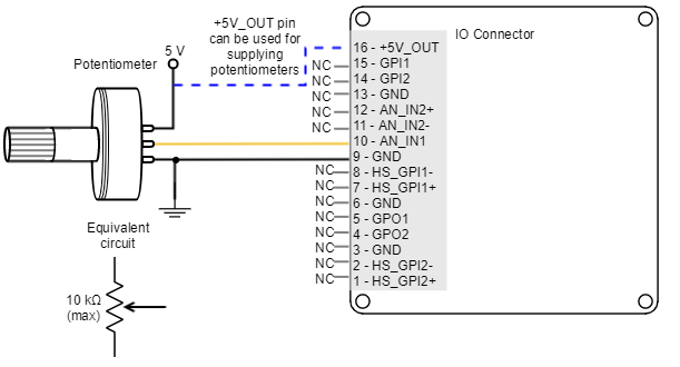
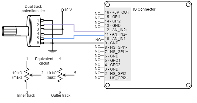
Position, velocity or torque targets can also be controlled trough an analog signal. Any general purpose analog input can be used as command source. Jupiter Servo Drive has two 12-bit analog inputs, a single ended one with 0 V to 5 V range (AN_IN1) and a differential one with +/-10 V range (AN_IN2). Refer to I/O Connections for further details about analog inputs.
A common application of the analog command source is the use of joysticks (or other kinds of potentiometers) for controlling the position or velocity of a system. As application examples, the following figures show how to connect a potentiometer to the single ended analog input (AN_IN1) and a dual track potentiometer to the differential analog input (AN_IN2).
Step and direction
For this command source, the drive typically accepts two digital inputs from an external source: Step (pulse) and Direction. Direction signal sets the direction of rotation (i.e., logic low or "0" for clockwise rotation and logic high or "1" for counter-clockwise rotation). Pulse signal is usually a square signal and each pulse on this signal causes the controller to move the motor one step in that direction. This command source can be used only for position mode.
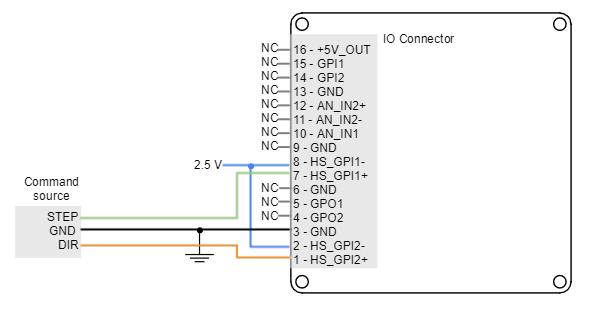
This command source is interfaced through high-speed digital inputs. HS_GPI1 is used for Step input, and HS_GPI2 is used for Direction input. Refer to I/O Connections for further specifications about high-speed digital inputs. Next figures illustrate how to connect a single ended and differential step and direction command source to the Jupiter Servo Drive.
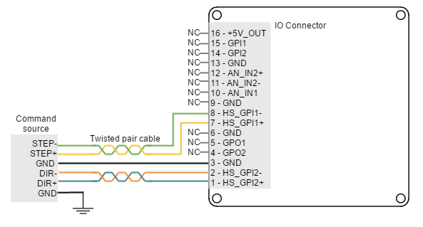
Single ended operation
In order to use the high-speed digital input in single ended mode, connect the negative terminal (HS_GPIx-) to 2.5 V. This voltage can be achieved with a voltage divider from +5V_OUT.
For a 24 V input, the negative terminal (HS_GPIx-) can be connected to 5 V (+5V_OUT).
PWM command
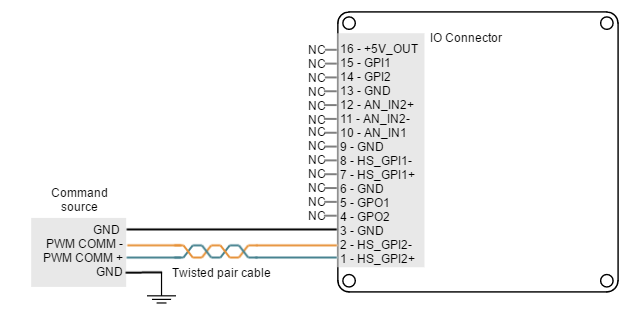
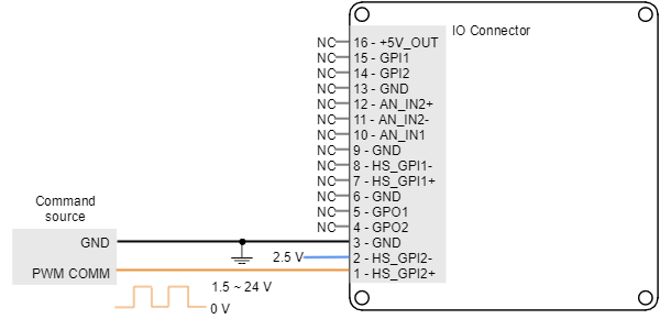
PWM command source sets a position, velocity or torque target from the duty cycle value of a PWM signal. PWM command has to be interfaced with the high-speed digital input 2 (HS_GPI2). Further details about this input can be seen in I/O Connections page. PWM command sources with single and dual input modes can be used.
It is recommended to use a PWM frequency between 2 kHz and 20 kHz. Higher frequencies could be read but will lead to a lower resolution with no improvement in performance. Frequencies below 2 kHz can lead to control problems.
Single input mode
Single input mode is based o the use of a PWM signal whose duty cycle sets the target position, velocity or torque. A duty cycle of 50% corresponds with a target of 0 rad, 0 rpm or 0 N·m, and higher or lower values indicate the target in a different rotating direction. That is, a duty cycle of 0% corresponds with the maximum position, velocity or torque in one direction, and a 100% duty corresponds to the maximum position, velocity or torque in the opposite direction.
Examples of single input mode PWM command in differential and single ended connections are shown in the next figures.
Dual input mode
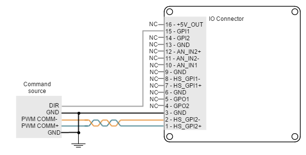
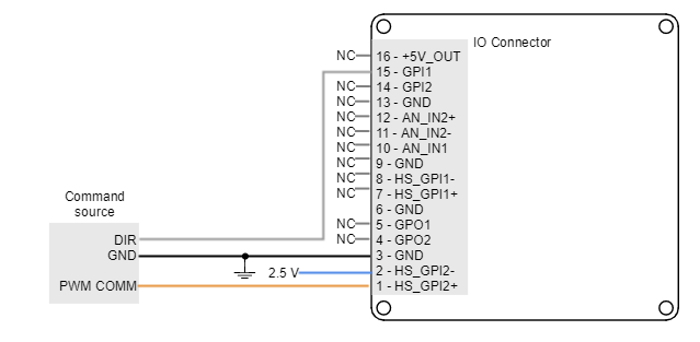
Dual input mode uses two signal lines, a PWM signal whose duty cycle sets the target position, velocity or torque, and a Direction signal that indicates the rotation direction (i.e., logic low or "0" for clockwise rotation and logic high or "1" for counter-clockwise rotation). In this mode, a duty cycle of 0% corresponds with a target of 0 rad, 0 rpm or 0 N·m, and a duty cycle of 100% corresponds to the maximum position, velocity or torque.
Two general purpose inputs are used:
- High speed digital input 2 (HS_GPI2) for PWM Command
- General purpose digital input 1 (GPI1) for Direction.
Examples of dual input mode PWM command in differential and single ended connections are shown in the next figures.
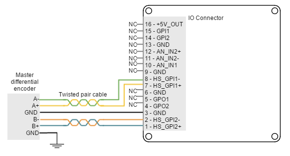
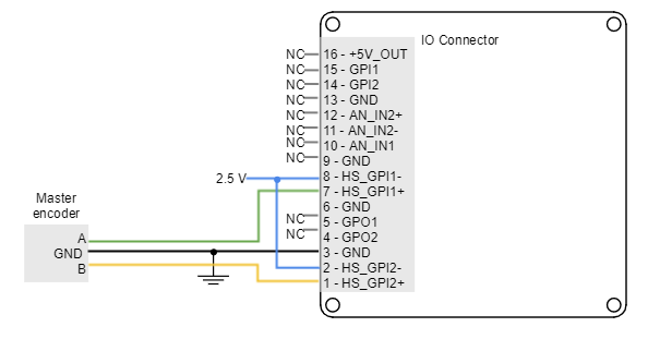
Encoder following or electronic gearing
Encoder following command source is used tor drive two motors to the same position. The encoder (or an auxiliary encoder) of the master motor is read by the Jupiter Servo Drive and used as position target. A gearing ratio between the motors (input counts to output counts ratio) can be configured via software.
Encoder following command source is implemented by connecting the input encoder (auxiliary encoder of the master motor) to high-speed digital inputs (HS_GPI). Encoder channel A must be connected to high speed digital input 1, and channel B to high speed digital input 2. Connection examples for the differential and single ended master encoders are shown in the next figures: