Motor and shunt braking resistor
AC and DC brushless motors
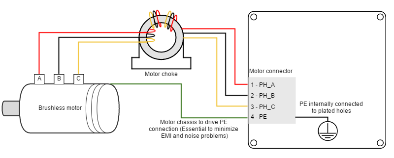
Brushless motors should be connected to phase A, B and C terminals. Note that some manufacturers may use different phase name conventions (see Table below). Motor wiring is an important contributing factor to Electromagnetic Interferences, please check this document regarding Electromagnetic Compatibility in servo drives Electromagnetic Interference Issues With Servo Drive Systems.
Phase name | Alphabetic | Numeric | UVW |
|---|---|---|---|
PH_A | A | 1 | U |
PH_B | B | 2 | V |
PH_C | C | 3 | W |
Common-mode choke
In order to minimize EMI that can affect sensitive signals, the use of a motor choke is recommended. The objective of the motor choke is to block the common mode current to the motor and cables. While using a separate choke for each phase could also work, the EMI reduction would be much lower than passing all the phases through the same choke.
Proper three-phase motor choke wiring
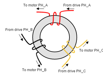
In order to minimize the capacitive coupling of the motor wires, and therefore cancelling the effect of the common mode rejection effect, the choke has to be properly wired.
- An excessive number of turns causes a high capacitive coupling. Only 2 or 3 turns per motor phase are recommended.
- For reducing the coupling between phases, space the phases 120º apart. Start each phase wire in the same rotating direction, wrapping all phases clockwise or anticlockwise. This will add the common mode flux and increase its impedance.
DC motors and voice coil actuators
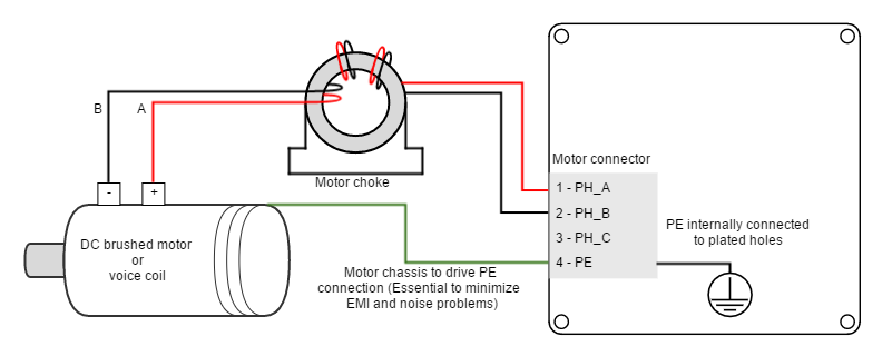
DC motors and voice coil actuators are connected to phase A and phase B terminals. Phase C terminal is left unconnected.
Common-mode choke
In order to minimize EMI that can affect sensitive signals, the use of a motor choke is recommended. The objective of the motor choke is to block the common mode current to the motor and cables. While using a separate choke for each phase could also work, the EMI reduction would be much lower than passing all the phases through the same choke.
Proper DC motor choke wiring
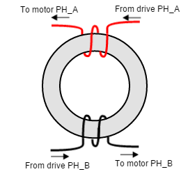
In order to minimize the capacitive coupling of the motor wires, and therefore cancelling the effect of the common mode rejection effect, the choke has to be properly wired.
- An excessive number of turns causes a high capacitive coupling. Only 2 or 3 turns per motor phase are recommended.
- For reducing the coupling between positive and negative, space them 180º apart. Start positive and negative wire in the same rotating direction, wrapping both phases clockwise or anticlockwise. This will add the common mode flux and increase its impedance.
Motor wiring recommendations
Other wirings
Refer to the "Safe Torque Off (STO), motor temperature and brake wiring" section for detailed wiring instructions on safety systems like the motor temperature sensor.
Wire section
The minimum wire section is determined by the motor current. It is preferred to use wide section stranded wires to reduce impedance, power losses and ease the assembly. Insulator size should not exceed connector pitch
- For JUP-20/80 and JUP-15/170, insulator size should not exceed 5 mm.
- For JUP-40/80 and JUP-30/170, insulator size should not exceed 6.35 mm.
Following table indicates recommended section for JUP-20/80 and JUP-15/170:
Connection | Minimum wire size | Maximum wire size |
|---|---|---|
| Stranded wire (preferred) | 1.5 mm2 (15 AWG) | 4 mm2 (12 AWG) |
| Solid wire | 1.5 mm2 (15 AWG) | 4 mm2 (12 AWG) |
Following table indicates recommended section for JUP-40/80 and JUP-30/170:
Connection | Minimum wire size | Maximum wire size |
|---|---|---|
| Stranded wire (preferred) | 2 mm2 (14 AWG) | 4 mm2 (12 AWG) |
| Solid wire | 3 mm2 (12 AWG) | 6 mm2 (10 AWG) |
Wire ferrules
For low power applications, it is recommended to use wire ferrules to prevent cable damage or wrong contacts. For higher power applications, direct cable connection is recommended, since it provides lower contact resistance.
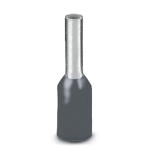
Due to connector's size, ferrule size is limited. For the JUP-20/80 and JUP-15/170 versions the maximum allowed ferrule size is 3 mm2. Ensure the insulator is does not exceed 5 mm (connector pitch). Following are some suggested ferrules for JUP-20/80 and JUP-15/170:
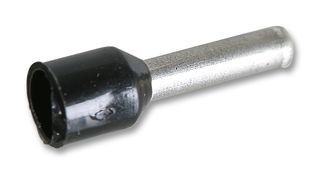
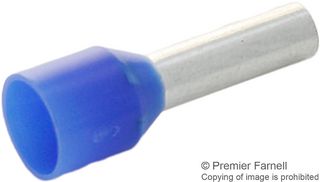
Due to connector's size, ferrule size is limited. For the JUP-40/80 and JUP-30/170 versions the maximum allowed ferrule size is 4 mm2. Ensure the insulator is does not exceed 6.35 mm (connector pitch). Following are some suggested ferrules for JUP-40/80 and JUP-30/170:
Manufacturer | Part number | Image | Description |
|---|---|---|---|
| Phoenix Contact |
| 4 mm2 (12 AWG) |
Motor choke
In applications where electromagnetic compatibility is a concern or that must comply with the EMC standards, the use of an external common mode choke is necessary. Some choke wiring recommendations are:
- Place the choke as close to the drive as possible.
- Make sure the chosen choke does not saturate at the maximum operating phase current. If this happens, the choke temperature would increase rapidly.
- Only 2 or 3 turns of the motor cables to the choke are recommended for best performance. Doing more than 3 turns reduces choke effectiveness, as capacitive coupling between wires would bypass the choke effect.
- PE conductor should NOT pass through the choke.
- Avoid contact of the toroid core with a grounding point.
Next table shows recommended chokes for the Jupiter Servo Drive.
Type | Manufacturer | Part number | Remarks |
|---|---|---|---|
| Output Choke | Emikon | ||
| Ferrite cable core | Laird Technology | LFB360230-300 | Preferred. Perform 1 or 2 turns depending on your cable width. |
| Ferrite cable core | Laird Technology | ||
| Ferrite cable core | Laird Technology | ||
| Ferrite cable core | Laird Technology | ||
| Output Choke | Roxburgh |
Wire length
- The distance between the Jupiter Servo Drive and the motor should be minimized when possible. Short cables are preferred since they reduce power losses as well as electromagnetic emissions and immunity.
- Avoid running motor wires in parallel with other wires for long distances, especially feedback and signal wires.
- The parasitic capacitance between motor wires should not exceed 10 nF. If very long cables (> 100 meters) are used, this value may be higher. In this case, add series inductors between the Jupiter outputs and the cable. The inductors must be magnetically shielded, and must be rated for the motor surge current. Typical values are around 100 μH.
Shunt braking resistor
While decelerating a motor (abrupt motion brakes or reversals), the mechanical energy is converted into electrical energy by the motor. This energy is regenerated into the power supply and could lead to an increase of the supply voltage. To absorb this energy the Jupiter incorporates a shunt transistor to connect an external braking resistor.
Wiring recommendations of the shunt braking resistor:
- The external braking resistor should be connected between SHUNT_OUT and POW_SUP terminals of the Jupiter Supply and shunt connector.
- It is strongly recommended to use an external fuse to limit the maximum power dissipation according to the chosen shunt resistor.
- Wire section should be, at least, like the motor wires.
- Shunt resistor connections should be as short as possible to reduce parasitic inductances.
Shunt resistor calculation tool
Additional information on shunt braking resistor sizing and a calculation tool can be found here.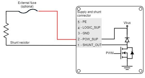
Hot surfaces
Be careful, shunt resistor may have hot surfaces during operation.
Configuration of the shunt
The shunt transistor can be configured using parameters in the register 0x2103 - Shunt configuration. When the supply voltage reaches the maximum voltage indicated in register 0x2101 - Drive bus voltage, the shunt transistor is activated.
As a recommendation, set the DC bus voltage limit above the maximum expected DC supply voltage + 5%.
When using batteries set the DC bus voltage limit below the maximum charge voltage. This will allow regenerative braking and protect the battery against overcharging.