Primary Absolute Slave 1
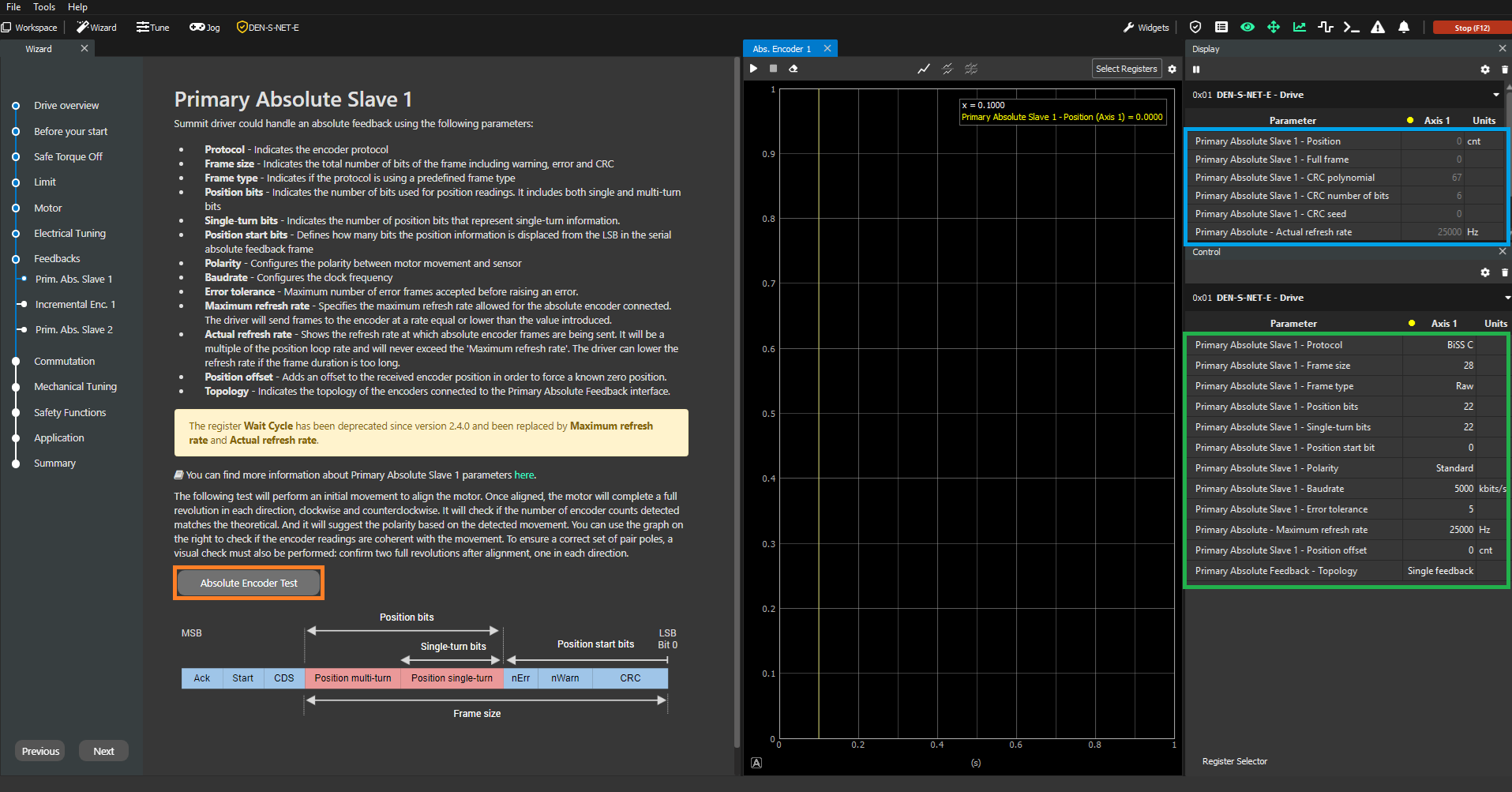
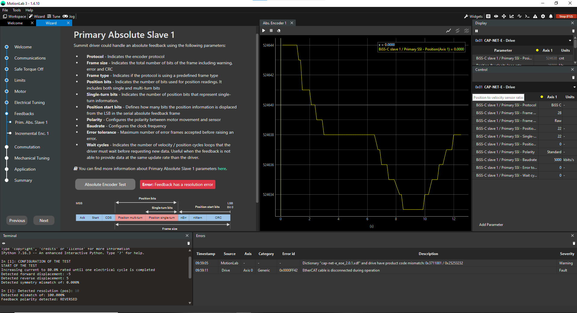
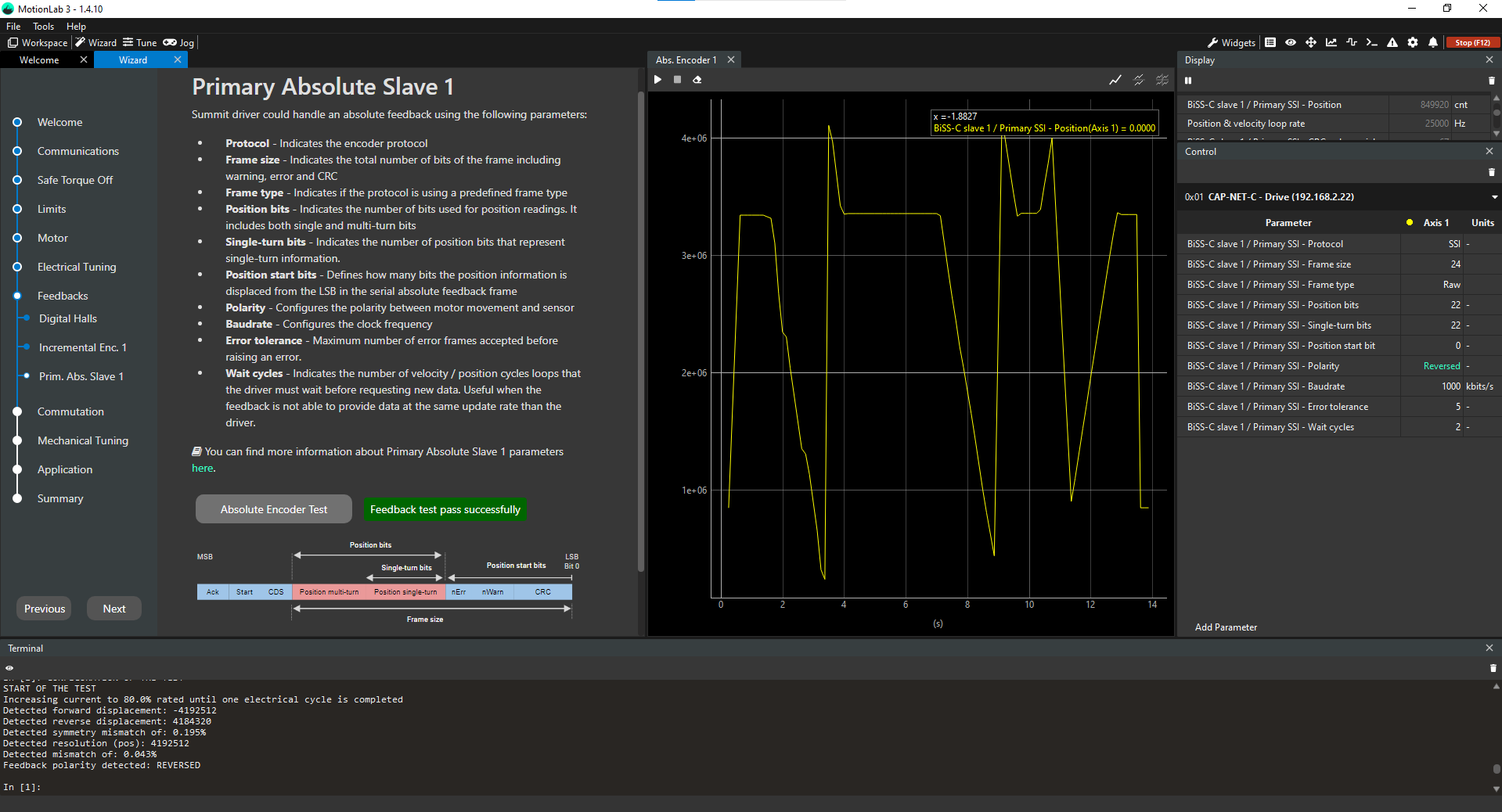
This step explains how to configure the primary absolute encoder properly in the configuration Wizard. In order to do it, you need to properly fill the parameters associated with this encoder in the Control widget (green square below). After this, you can validate that the position readings are correct both by taking a look at the values in the Display widget (blue square below) and performing the absolute encoder test (orange square below) in order to make sure that the encoder readings and pole pairs settings of the motor are correct.
Parameters to configure
Protocol → Indicates if the encoder protocol is SSI (value of 1) or BiSS-C (value of 0)
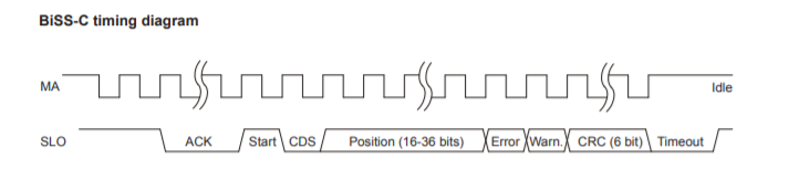
Frame size → Indicates the total number of bits of the frame. These include position bits, special bits, warning, error and CRC bits, etc.
Start, CDS and ACK bits do not need to be included in this frame size.
Frame type → Indicates the format of the received frame. This parameter allows parsing frames in a specific way. For example, the BiSS-C BP3 profile frame type will assume there is CRC, error and warning bits and will use them to detect errors in the frame. For unsupported frame types, use raw or raw gray modes. These modes allow to read the position from any frame type without processing special bits such as CRC or error flags
Position bits → indicates the total number of bits used for position readings. This includes single-turn and multi-turn bits.
Single-turn bits → Indicates the number of bits that represent single-turn position data.
Position start bit → Defines how many bits the position information is displaced from the LSB in the serial absolute feedback frame.
Polarity → the polarity of the feedback sensor is a parameter that relates how the position readings change when a positive voltage is applied to the phases of the motor. It can either be "Standard" or "Reversed".
Understanding how the polarity works
If with polarity set as "Standard, the position increases when a positive voltage is applied, then the polarity is correct as "Standard". On the other hand, if the position readings were to decrease, then the polarity setting would be wrong and you would need to change it to "Reversed" for this particular feedback sensor. Having a correct polarity setting is essential to having the sensor working properly and this is exactly what the absolute encoder test is meant to determine. On an additional note, the polarity of the digital halls does not relate to the polarity of any other feedback sensor in the system (they can be the same or opposite, it does not matter).
Baudrate → maximum baudrate of the SSI encoder in kbits/s.
Limitations of total frame size and total position data
There are certain limitations in the firmware implementation as far as the maximum frame size and the number of position bits that the primary absolute encoder can have. The following restrictions apply:
Maximum frame size → 64 bits
Maximum position data → 32 bits
This means that any encoder with a frame larger than 64 bits will not be read correctly from the drive (even if the position data bits are <= 32 bits).
In addition to this, there are additional limitations applied when the system has 2 BiSS-C encoders in daisy chain fashion:
BiSS-C slave 1 frame size + BiSS-C slave 2 frame size <= 64 bits
BiSS-C slave 1 positions bits + BiSS-C slave 2 position bits <= 48 bits
Common question: Can I operate a 44 bits BiSS-C encoder with 16 single-turn bits and 20 multi-turn bits with our drive then?
Answer: Yes, you can use it with our drive but you will lose the 4 most significant multi-turn bits of the encoder in order to comply with the 32 total bit limit. See the third example below to observe how an encoder like this is configured.
Topology → Indicates the topology of the encoders connected to the Primary Absolute Feedback interface. Please refer to register: 0x2395 - Primary Absolute Feedback - Topology .
Examples:
Zettlex INC-X-XXXX-191001-SSI1-XXXX-X-X (19 single-turn bits, SSI)
Protocol → 1 (SSI)
Frame size → 24
Frame type → 0 (raw)
Position bits → 19
Single-turn bits → 19
Position start bit → 0
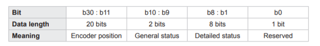
RLS MHA-X-DCH-20M-XX-X-XX (16 single-turn bits, 20 multi-turn bits, BiSS-C)
Protocol → 0 (BiSS-C)
Frame size → 44
Frame type → 0 (raw)
Position bits → 32
Single-turn bits → 16
Position start bit → 8
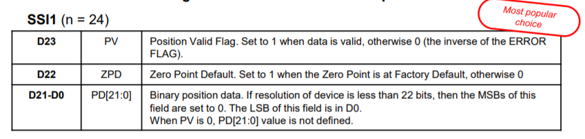
RLS MHA-X-SCX-18B-XX-X-XX (18 single-turn bits, SSI)
Protocol → 1 (SSI)
Frame size → 29
Frame type → 0 (raw)
Position bits → 18
Single-turn bits → 18
Position start bit → 11
Absolute encoder test
This test has the following purposes:
Validate that the absolute encoder parameters and pole pair parameters introduced by the user are correct → this is done by moving a certain predefined range of motion and counting the position readings so if they match with the expected ones then the test turns successful. If they do not match, then you get a failure and you need to recheck both parameters to see which one could be wrong.
Determine the polarity of the absolute encoder → this is done by applying always positive voltage first and then negative voltage and seeing how the position readings change. Please note that this polarity determination is not done if the previous validation does not turn out successfully.
Therefore, this test has only two possible outcomes:
Failed test
Success test
Absolute encoder quick verification
If you get a failure in this test, a quick check that you can do is verify the resolution of the encoder by moving the shaft manually one full revolution (motor is disabled) and checking that the position readings (blue square in the initial picture) change in an increment equal to 2^number of single-turn bits. This will validate the single-turn, the position starting bit, the frame size and type parameters. In a system with a gearbox, this can be trickier but you could move the motor in voltage mode (using the Jogs) and check that a full revolution on the output equals an increment in position readings equal to (2^number of single-turn bits) * gear ratio of the gearbox.
Troubleshooting:
The Feedback test in MotionLab3 fails although my parameters are set correctly
The feedback test within MotionLab3 uses the number configured in the pole pairs register to check the resolution of the encoder. If you experience the following symptoms:
The encoder is configured correctly
The encoder test fails
The terminal shows unexpected detected resolution
then, it is likely that the pole pairs of the motor are not set correctly.
Please go back to Motor → General within the MotionLab3 wizard to configure. Alternatively, use one of the following registers depending on the drive type: 0x106 - Motor pole pairs (for CORE drives) or 0x2106 - Motor pole pairs (for NET and XCR drives).
Please note that the parameter requires entering the number of pole pairs and not total number of poles.