Alternative Commutation Method - Dynamic Forced Phasing
Feature Overview
Dynamic Forced Phasing is an calibration routine used to align a drive’s electronic commutation with a brushless motor’s physical rotor position. By applying a rotating current vector to the stator, the drive forces the motor into a controlled, open-loop rotation. During this movement, the drive maps the feedback device’s position against the electrical cycle to calculate the precise commutation offset required for efficient closed-loop operation.
This feature solves the critical issue of commutation misalignment, which typically occurs when integrating third-party motors or replacing feedback hardware in the field. Without proper alignment, systems suffer from high heat, audible noise, and significantly reduced torque. Unlike static "snap" methods that can fail due to high friction or gravity on vertical axes, Dynamic Forced Phasing utilizes motion to overcome mechanical resistance. This ensures a highly accurate calibration even in demanding real-world environments where the motor cannot easily settle at a stationary electrical zero.
The primary benefit of this approach over traditional binary search methods is that it mitigates high static frictions in the system by using motion. This combined with data points over multiple electrical cycles, to accommodate for any feedback inaccuracies, and both directions leads to a more accurate phasing. Ensuring that the motor is commutating efficiently for the best performance possible.
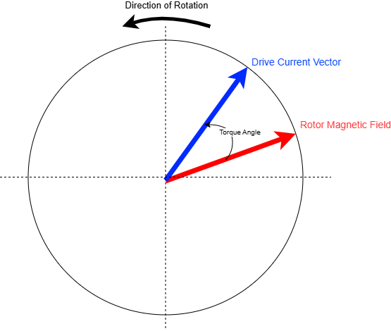
Servo Motor Phasor Diagram
Technical Implementation
To implement Dynamic Forced Phasing, the drive must first be configured in a specialized open-loop current mode, bypassing the standard velocity and position loops. The user defines a commutation current, the higher the better, and a target frequency for rotation. Once initiated, the drive generates a three-phase sinusoidal current vector that rotates at a constant rate. This creates a rotating magnetic field in the stator that "drags" the rotor along, effectively treating the servo as a high-pole-count stepper motor to ensure predictable, synchronous motion.
As the motor moves, the drive will poll samples from the incoming feedback signals from the encoder based on the preconfigured settings. By correlating the commanded electrical angle of the current vector with the reported mechanical position from the feedback device, the phase lag or offset can be calculated. Sophisticated implementations perform this measurement over several revolutions to average out the effects of mechanical friction, cogging torque, and encoder eccentricity. This multi-point sampling ensures that the resulting commutation angle is statistically optimized for the entire 360-degree rotation of the shaft.
Procedure
Before proceeding with this procedure please ensure that you have configured the drive up to the commutation step in the configuration wizard. These include: safe torque off, limits, motor data, current loop tunings, and feedbacks. Your actuator must be using a high-resolution absolute encoder as the reference feedback.
The following workspace has been preconfigured to help aid in this process: Phasing_open_loop.xws
Configure the drive to rotate in open-loop (internal generator) and 0x2014 - Operation mode to current mode.
0x2151 - Commutation feedback sensor = Internal Generator (3)
0x2380 - Generator mode = Saw-tooth (1)
0x2154 - Phasing mode = No Phasing (2)
Set the 0x2153 - Reference feedback sensor to the high-resolution rotor encoder.
Set the 0x2150 - Commutation angle offset and 0x2152 - Reference angle offset to 0, if they aren't already 0
Configure the workspace to capture the Commutation Angle and Reference Angles at high frequency (monitoring). Capture it in the rising or falling edge from 1 to 0 of the Commutation Angle. This is preconfigured in the attached workspace. For more information about this process please refer our product manual: System diagnosis tools: Monitoring & Disturbance.
Configure a positive rotation (0x2382 - Generator gain = 1, 0x2383 - Generator offset = 0) and a low 0x2381 - Generator frequency - 0.1 Hz
Start rotating with a small current. Increase to 0x201B - Current direct set-point.
Calculate the offset between Commutation Angle and Reference Angle
Off_pos = Comm_Angle - Ref_Angle
Be sure that the offset is stable and constant. Otherwise reduce frequency or increase current.
The Commutation Angle and the Reference Angle should be taken as close to their intersection as possible.
Configure a negative rotation (0x2382 - Generator gain = -1, 0x2383 - Generator offset = 1), a low 0x2381 - Generator frequency- 0.1 Hz, and change the monitoring trigger to rising edge
Start rotating with a small current. Increase to 0x201B - Current direct set-point.
Calculate the offset between Commutation Angle and Reference Angle
Off_neg = Comm_Angle - Ref_Angle
The same current as the positive test should be sufficient for the negative test
The commutation Angle and the Reference Angle should be taken as close to their intersection as possible.
Calculate the total Commutation Angle Offset by averaging both results
Comm_Angle_Offset = (Off_pos +Off_neg) / 2
Gathering multiple offset points across different electrical revolutions and averaging them can increase the accuracy of the results.
Positive Direction Test
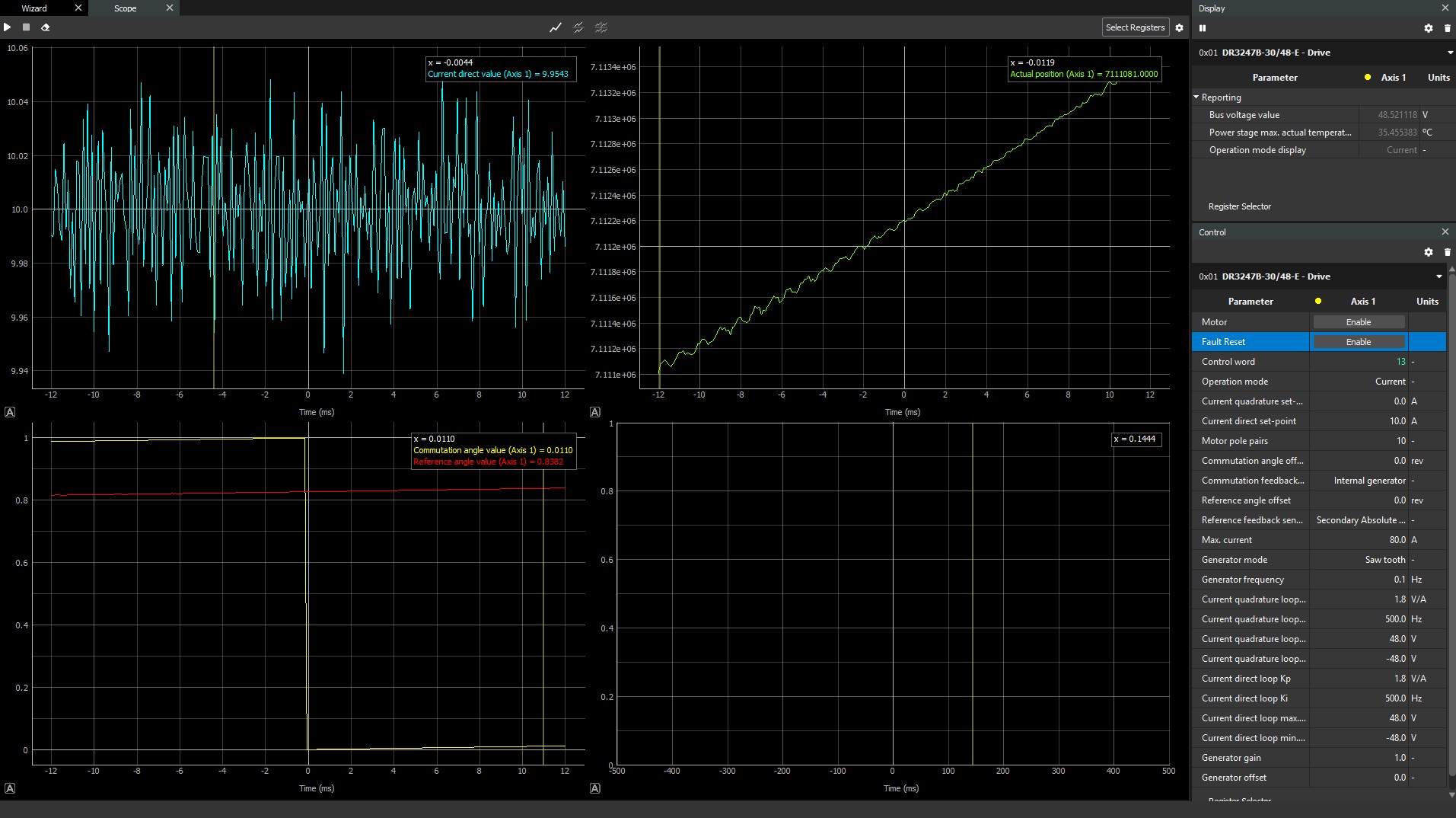
Commutation Angle Calculation was 1 - 0.8273
Negative Direction Test
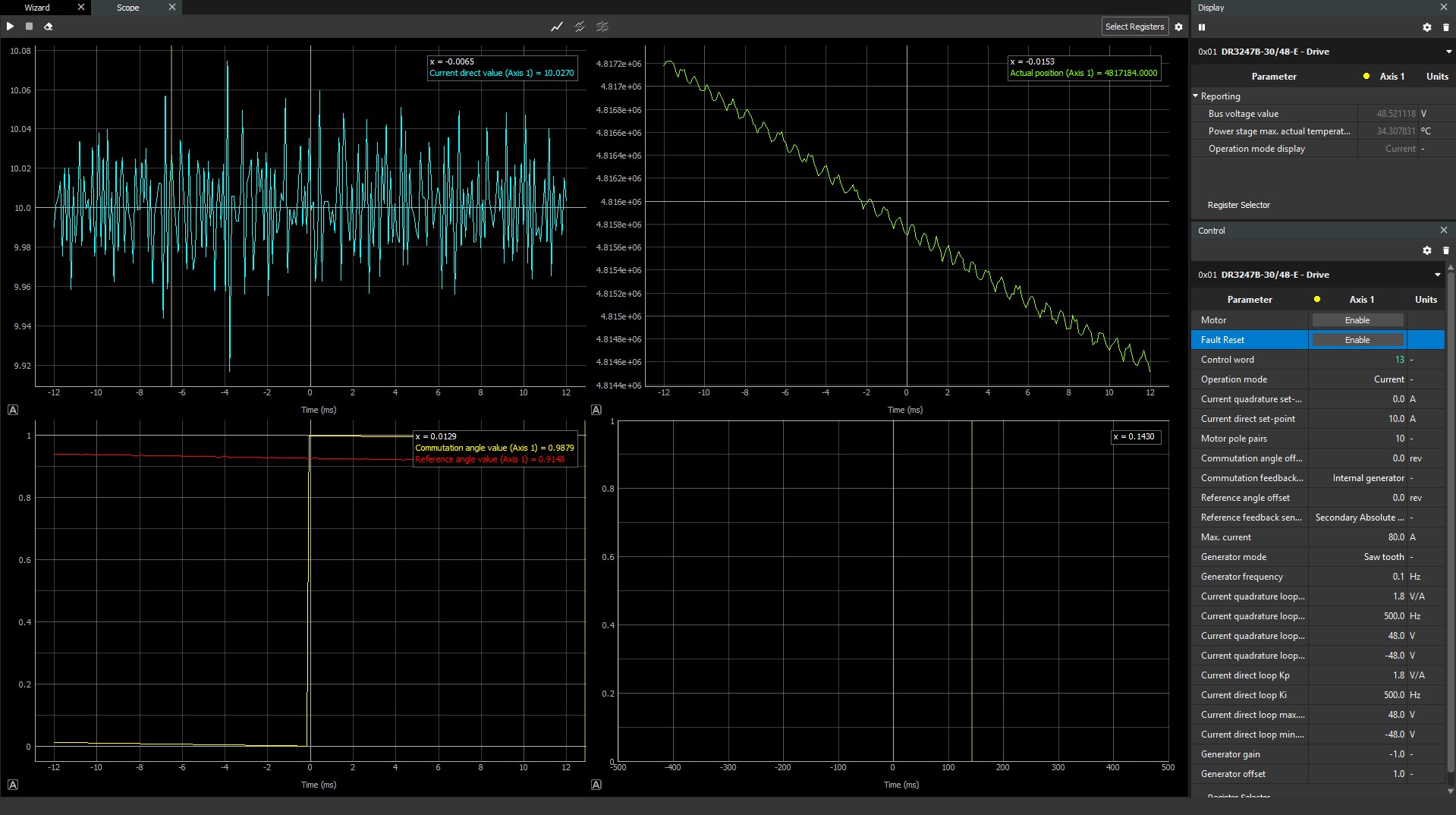
Commutation Angle Calculation was 1 - 0.9262
With these numbers the commutation and reference angle was found to be 0.12325 [(0.1727+0.0738)/2]. This angle was entered and then check with the drive's internal commutation analysis test.
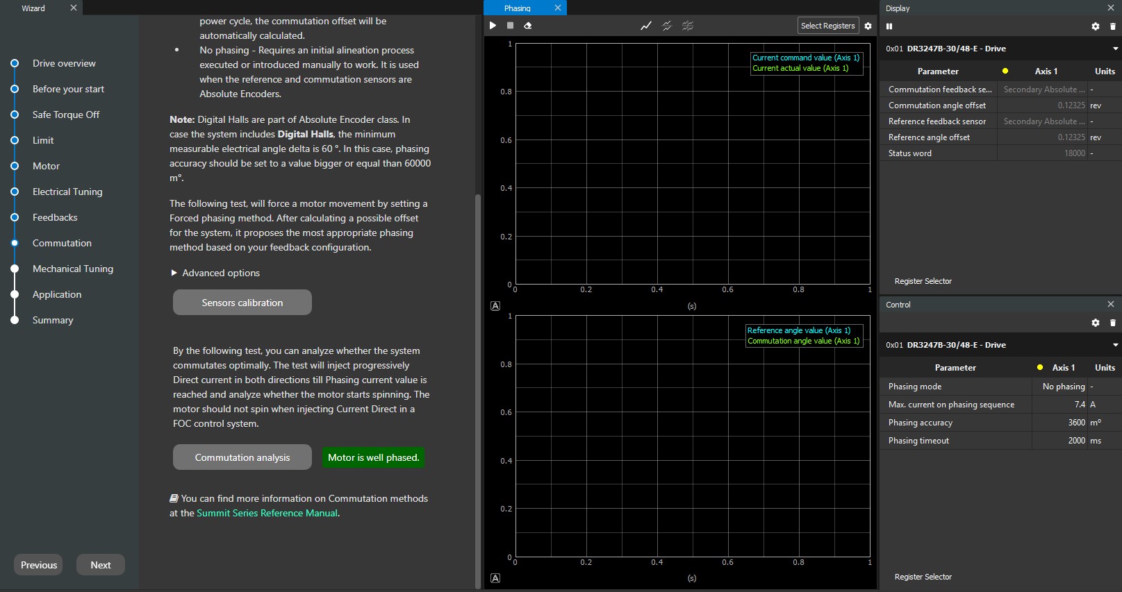
Positive Phasing Check