Primary Absolute Slave 2 (daisy chain)
Summit servo drives support two BiSS-C feedbacks connected to the Primary interface. These feedbacks can be connected in daisy-chain or in Dual BiSS-C (two positions in the same BiSS-C frame). This section describes how to configure the second feedback.
BiSS-C is a serial protocol that offers a series of advantages. These (amongst others) are:
It has a standard protocol definition
Contains error and warning bits and provides CRC checking
It allows for daisy chain operation.
More information about the BiSS-C protocol can be found below:
BiSS-C BP3 profile description
BiSS-C BP1 profile description (Not recommended for new designs. Please refer to BiSS Profile 3).
The following picture shows an example of a BiSS-C daisy chain frame. The example frame is divided into two segments, each containing data of each separate feedback.

Note
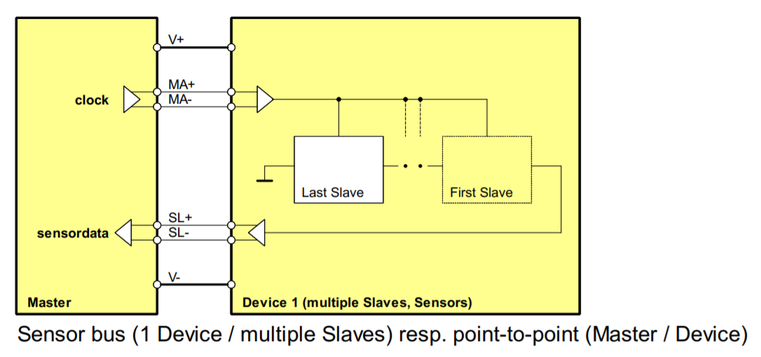
Summit servo drives only support the BiSS-C unidirectional and point to point topology (shown below). The ACK, Start, and CDS bits are automatically taken into account by the drive
Daisy chain operation for EtherCAT/CANopen Drives
Daisy chain operation is supported in BiSS-C. The BiSS-C slave 2 encoder module is completely dependent on the BiSS-C slave 1 / Primary SSI encoder. To be able to use this feedbacks in a daisy chain, both feedbacks (this one and BiSS-C slave 1 / Primary SSI encoder) need to be configured separately, both selected as feedback somewhere, and the Primary Absolute Feedback - Topology needs to be specified as Two Slaves in the daisy-chain.
Before FW version 2.9.0, you needed to specify the number of feedbacks in the chain instead of the topology. The topology parameter is backwards compatible with the number of feedbacks in the chain option.
When using daisy chain, the total frame size is made up of the START and CDS bits plus the BiSS-C slave 1 / Primary SSI encoder frame size and the BiSS-C slave 2 frame size combined. This combination must fit the maximum frame size.
Since the total frame size includes the START and CDS bit, the meaningful data that can be captured in daisy chain configuration is limited to 62 bits
Dual Biss-C operation for EtherCAT/CANopen Drives
The absolute encoder module supports handling two encoder positions in the same BiSS-C frame. The two positions are considered to be from different slaves (even though there is only one physical slave), and they need to be configured separately, and the Primary Absolute Feedback - Topology needs to be specified as Dual Biss-C.
The following registers of the Primary Absolute feedback - Slave 1 and Primary Absolute feedback - Slave 2 must share the same configuration:
Protocol
Frame size
Frame type
Polarity
To correctly parse the frames, the following parameters must be configured correctly and independently for each slave
Position bits
Single-turn bits
Position start bit
A set of parameters are available to the user to adapt the slave absolute interface to the different frame types:
Frame size. Indicates the total number of bits of the second slave's frame. These include position bits, special bits, warning, error and CRC bits, etc.
0x2400 - Primary Absolute Slave 2 - Frame size
ACK, START and CDS bits should not be included in this parameter
Please be aware that the maximum frame size depends on the Actual refresh rate and the Baudrate. Larger frame sizes (over 40 bits) may require higher baudrates.
Error tolerance. The drive can detect errors in frames, such as the error bit and CRC in the BiSS-C protocol. If an incorrect frame is detected, it is dropped and the drive keeps the last read as current position actual. However, if too many followed errors are detected, the drive generates a fault and stops the operation. This register specifies the number of errors accepted before generating the fault.
0x2401 - Primary Absolute Slave 2 - Error tolerance
Setting a 0 value will ignore any error from the encoder.
Polarity. Indicates the direction of rotation of the encoder. 0 value applies standard polarity (read directly from the feedback) and a value different than 0 reverses the polarity.
Frame type. Indicates the format of the received frame. This parameter allows parsing frames in a specific way. For example, the BiSS-C BP3 profile frame type will assume there are CRC, error and warning bits and will use them to detect errors in the frame
0x2404 - Primary Absolute Slave 2 - Frame type
For unsupported frame types, use raw or raw gray modes. These modes allow reading the position from any frame type without processing special bits such as CRC or error flags.
Note
Frame type 3 implements the BiSS-C BP3 profile. By selecting this frame type, the first 8 bits will automatically be used for CRC and error checking, since a BP3 BiSS-C frame is assumed. More information about this profile can be found here
With BiSS-C BP3 type selected, frames with errors will be discarded.
Position bits. Indicates the number of bits used for position readings.
0x2405 - Primary Absolute Slave 2 - Position bits
Note
The device calculates its own multi-turn data to allow covering the whole position variable range. Use position range configuration if the systems needs to work only in the absolute encoder range
Single-turn bits. Indicates the number of position bits that represent single-turn information.
0x2406 - Primary Absolute Slave 2 - Single-turn bits
This information is used by the drive to compute the angle commutation properly. For multi-turn absolute encoders, this information gives the reference of 1 mechanical revolution to the drive.
For single-turn absolute encoders, position bits must be equal to single-turn bits.
Note
Writing the following parameters will cause the software multi-turn (multi-turn part calculated by the driver) to be reset to 0: Frame size, Polarity, Frame type, Position bits, Single-turn bits, Position start bit and Position offset
Position start bit. Defines how many bits the position information is displaced from the LSB in the serial absolute feedback frame.
Position offset. Adds an offset to the read encoder position (after polarity has been applied). Negative values on this parameter shift the overall position in the negative direction and positive values shift it to the positive direction
Position. Shows the encoder position value taking into account the polarity, position offset and (if available) software multi-turn.
Full frame. Contains last received frame including special bits, for debugging purposes
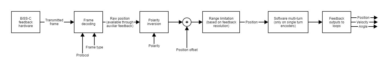
How the data is parsed
Bidirectional communication
This section is available from version 2.5.0 of some devices. Check the product manual to see if the feature is supported.
The drives have the capability of acting as a bridge for communicating the BiSS-C feedback through the Control communication.
Further details of BiSS-C protocol Control Communication is freely available on the official BiSS interface website.
The Control Communication allows to configure parameters of the connected feedbacks without interrupting the position readings. The drives allow to transmit and receive information to and from the encoder through this protocol.
For accessing the bidirectional interface, Summit devices implement 4 registers:
Register address
0x2440 - Primary absolute interface - Register address for the primary absolute feedback
Register data
0x2441 - Primary absolute interface - Register data for the primary absolute feedback
Operation status
0x2442 - Primary absolute interface - Operation status for the primary absolute feedback
Control
0x2443 - Primary absolute interface - Control for the primary absolute feedback
By means of these registers, we support access to the feedback registers (registers of the encoder itself). Each encoder has its own registers, for more information please refer to the datasheet of your encoder.
There are not different registers to access Primary Slave 2 (daisy chain). If you use a daisy chain, you will have to use the Control register to request the data from the second encoder. Please see the detail in the two procedures below.
Reading encoder registers
The procedure for reading an encoder register is the next one:
Read the Operation status and check that the absolute interface is idle. This means that the bidirectional interface is able to handle messages.
Write the address of the register to be read to the Register address.
Using Control write 0x01 for triggering a read operation of the indicated register. Alternatively, command “0x1001” can be used to access the second encoder if using daisy chain.
Double-check using register Operation Status that the bidirectional command has been executed properly (no error).
Read Register data, the content of this register corresponds to the data received from the encoder for the indicated register.
Writing encoder registers
The procedure for writing an encoder register is the next one:
Read the Operation status and check that the absolute interface is idle. This means that the bidirectional interface is able to handle messages.
Write the address of the register to be written to the Register address.
Write Register data with the desired value to be written to the register.
Using Control write 0x02 for triggering a write operation of the indicated register. Alternatively, command “0x1002” can be used to access the second encoder if using daisy chain.
Double-check using register Operation Status that the bidirectional command has been executed properly (no error).
(Optional) Read back the register to ensure that the data has been applied (follow the read encoder register procedure for that).