Implementation of PD Impedance Control
Feature Overview
PD impedance control is a robotics technique that makes a joint act like it is attached to a flexible spring (P - Proportional Gain) and a viscous damper (D - Derivative Gain). Instead of forcing the joint to rigidly hold a position, this form of control allows the joint to yield when touched, keeping it safe.
The proportional term defines the apparent stiffness by generating torque in response to position error, while the derivative term defines the apparent damping by responding to velocity error. Instead of trying to force a mechanism to follow a trajectory as rigidly as possible, PD impedance control shapes how the system reacts to deviations and external interaction forces.
While some control loops tell a joint to reach a target “no matter what”, potentially leading to dangerous impacts. PD Impedence control allows for safe human-robot interactions and smooth contact. This is important because it enables controlled, stable, and compliant motion, especially when a machine interacts with people, tools, or uncertain environments. By tuning stiffness and damping, the system can be made rigid for precision tasks or more compliant for safer contact and smoother force exchange. PD impedance control is commonly used in robotics, collaborative manipulators, exoskeletons, haptic devices, legged robots, and actuator-driven mechanisms where interaction behavior matters as much as position tracking.
Impedance Control Implementation
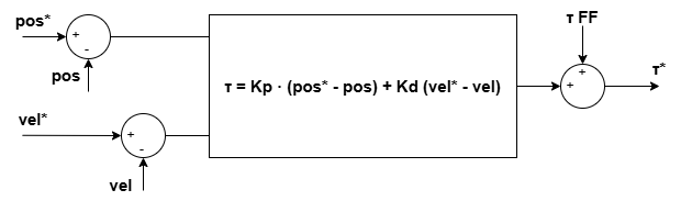
Considering a simplified PD impedance control loop:
where
K is the desired stiffness
D is the desired damping
qd is the position set-point
q’d is the velocity set-point
This model includes the following simplifications:
The “PD model” behaves as a spring-damper, without modelling inertia. The intrinsic joint inertia will be seen in real dynamics. This is usually enough in most applications.
Gravity/friction is assumed negligible or compensated externally → Use fo the Torque FF (torque offset) for gravity compensation. Depends on the robot kinematics so cannot be computed at drive level.
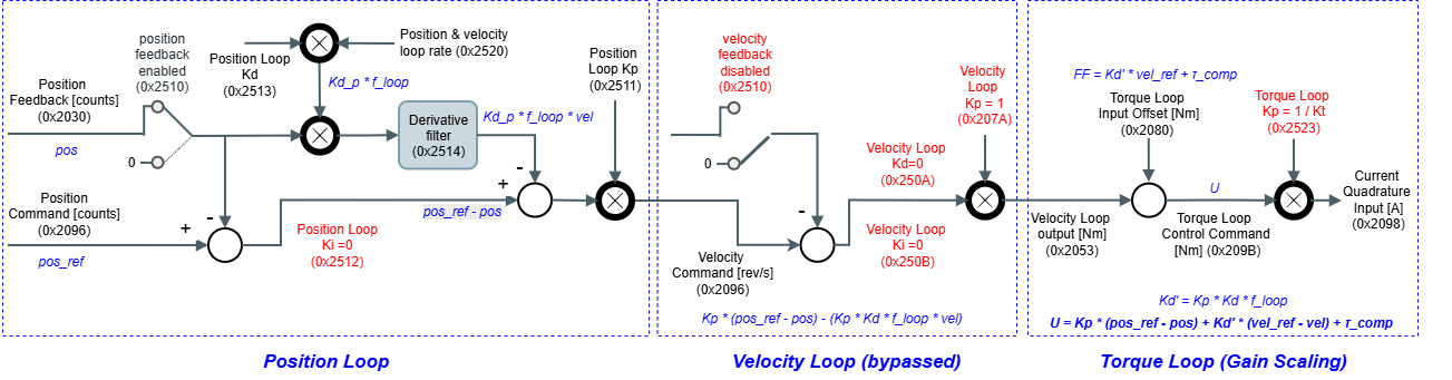
The resulting Impedance control is implemented at drive level as follows:
PD Control on Novanta Drives
The PD controller used in Impedance Control is not directly implemented in Novanta Drives, but can be used by re-configuring the position and velocity loops.
0x2014 - Operation mode: Position
Position Loop configured a P + D (derivative is done from position, not from position error)
Note that effective Kd'= 0x2511 - Position loop Kp * 0x2513 - Position loop Kd * 0x2520 - Position & velocity loop rate
Bypass the velocity loop
Velocity feedback disabled - 0x2510 - Control loops feedback options
Send the Kd * Vel_ref as a FF - 0x2080 - Torque loop input offset
Add any external compensation τ_comp (i.e friction and gravity) to the FF
Configure the Torque Loop to convert torque to current
0x2523 - Torque loop Kp = 1 / Kt (motor torque constant)
The following is a diagram of the resulting Control Loop