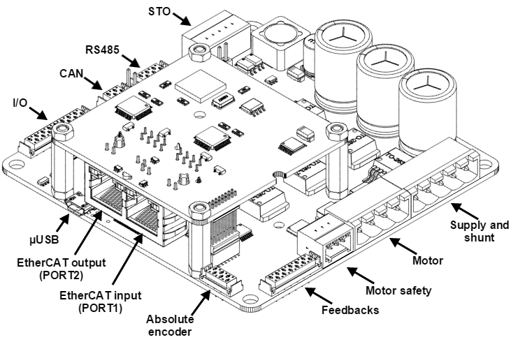
Connectors Guide
This chapter details the Jupiter Servo Drive connectors and pinout. Two Jupiter variants are detailed:
- Jupiter with USB/RS-232, USB/RS-485 and USB/RS-485/CANOpen (JUP-x/xx-S1, JUP-x/xx-S1 and JUP-x/xx-C)
- Jupiter with EtherCAT (JUP-x/xx-E).
Connectors position and pinout of Jupiter (JUP-x/xx-S1, JUP-x/xx-S2, JUP-x/xx-C)
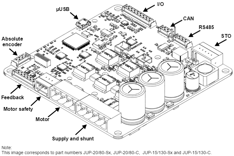
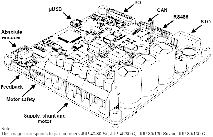
Jupiter Servo Drive presents different power connectors depending on its current rating:
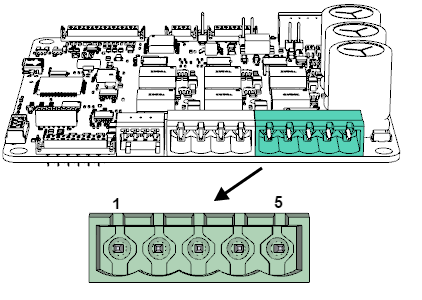
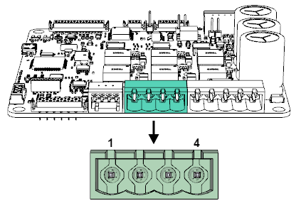
Connectors position in low-current Jupiter (JUP-20/80-y and JUP-15/130-y)
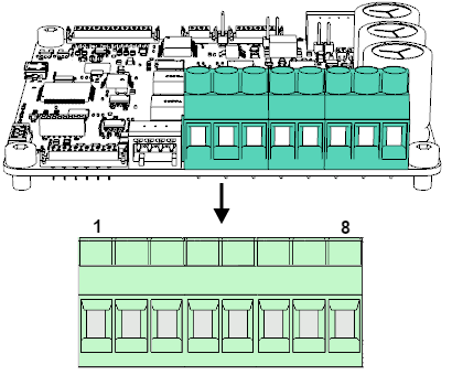
Connectors position in high-current Jupiter (JUP-40/80-y and JUP-30/130-y)
Pinout
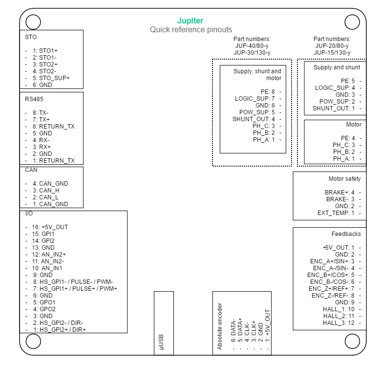
Supply and shunt connector (only JUP-20/80-y and JUP-15/130-y)
| P1 Connector | ||
|---|---|---|
Pin | Signal | Function |
1 | SHUNT_OUT | Shunt braking transistor output. Open drain output that connects to SHUNT_OUT to GND when DC bus votlage exceeds "Maximum user voltage" and the Shunt is enabled. |
2 | POW_SUP | Power supply input |
3 | GND | Ground connection |
| 4 | LOGIC_SUP | Logic supply input |
| 5 | PE | Motor protective earth connection, internally connected to motor PE and standoffs |
| Mating | |
|---|---|
| Description | Pluggable terminal block, 5 positions 5 mm pitch |
| Part number | |
Distributor codes | Digi-Key 732-2778-ND Farnell 1841344 Mouser 710-691352710005 |
| Notes | |
| |
Motor connector (only JUP-20/80-y and JUP-15/130-y)
| P2 Connector | ||
|---|---|---|
4 position 5 mm pitch pluggable terminal block. Wurth 691313710004 | ||
Pin | Signal | Function |
1 | PH_A | Motor phase A (Positive for DC and voice coils) |
2 | PH_B | Motor phase B (Negative for DC and voice coils) |
3 | PH_C | Motor phase C (Do not connect for DC and voice coils) |
| 4 | PE | Motor protective earth connection, internally connected to supply PE and standoffs |
| Mating | |
|---|---|
| Description | Pluggable terminal block, 4 positions 5 mm pitch |
| Part number | |
Distributor codes | Digi-Key 732-2777-ND Farnell 1841343 Mouser 710-691352710004 |
| Notes | |
| |
Supply, shunt and motor connector (only JUP-40/80-y and JUP-30/130-y)
| P3 Connector | ||
|---|---|---|
8 position 6.35 mm pitch screw terminal block. Phoenix Contact 1713927 | ||
Pin | Signal | Function |
1 | PH_A | Motor phase A (Positive for DC and voice coils) |
2 | PH_B | Motor phase B (Negative for DC and voice coils) |
3 | PH_C | Motor phase C (Do not connect for DC and voice coils) |
4 | SHUNT_OUT | Shunt braking transistor output. Open drain output that connects to SHUNT_OUT to GND when DC bus votlage exceeds "Maximum user voltage" and the Shunt is enabled. |
5 | POW_SUP | Power supply input |
6 | GND | Ground connection |
| 7 | LOGIC_SUP | Logic supply input |
| 8 | PE | Motor protective earth connection, internally connected to standoffs and the plate |
| Notes | ||
| ||
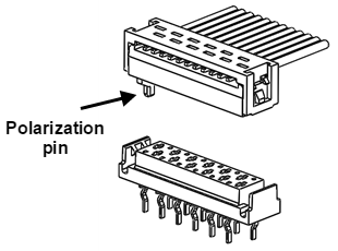
TE Micro-Match connectors mating
Most Jupiter Servo Drive signal connections are based in TE Micro-Match connectors. Two different wiring options can be used ribbon cable and multi-core crimped cable.
Ribbon cable
| Ribbon cable mating | ||
|---|---|---|
| Description | TE Micro-Match Male-on-Wire 1.27 mm pitch | |
| Image |
| |
| Cable | ||
| Use 0.5 mm² (24 AWG) flat cable. | ||
Easy wiring
Ribbon cable is the easiest and lowest cost option. It can be used together with wire splice connectors or solder sleeves.
For some applications, the fastest and reliable option is connecting the flat cable directly to the sensor, feedback or IO pins by means of a heat shrink solder sleeve.
Wiring accessory: wire to wire solder sleeve | |
|---|---|
| Description | Wire to Wire Solder Sleeve Heat shrinkable. Can be used to reliably connect flat Micro-Match wires to specific sensor, feedback or other thin wires. |
| Image |
|
| TE | B-155-9001 |
| Distributor code | Digi-Key A104848-ND |

Multi-core crimped cable
Multi-core crimped cable mating | |
|---|---|
| Description | TE Micro-Match housing connector 1.27 mm pitch |
| Image | 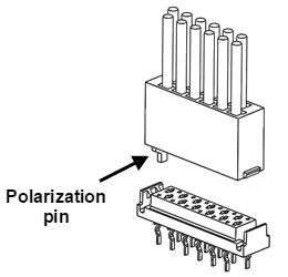 |
| Crimp terminals | |
| Description | Crimp terminal, male, 20-24 AWG |
| Image |  |
| Part number | |
Distributor codes | Farnell 1291807 Digi-Key A99491CT-ND Mouser 571-1-338097-1 |
| Cable | |
Use 0.2 ~ 0.5 mm² (20 ~24 AWG) flexible wires. | |
Clean wiring
Crimped single cables makes wiring cleaner and is a preferred option for volume applications.
Mechanical fixation for non-connected pins
Main mechanical subjection is provided by the fastening of male and female electrical pins. In order to increase mechanical subjection in applications where not all the pins are connected, it is important to put crimp terminals also in the pins without cable.
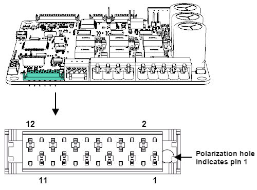
Feedback connector
| P4 Connector | ||
|---|---|---|
12 pin 1.27 mm pitch TE Micro-Match 1-338068-2 connector. | ||
Pin | Signal | Function |
1 | +5V_OUT | +5V 200mA max supply for feedbacks (shared with ansolute encoder and I/O connector) |
2 | GND | Ground connection |
3 | ENC_A+ / SIN+ | Single ended digital encoder: A input |
4 | ENC_A- / SIN- | Differential Encoder: A- input |
5 | ENC_B+ / COS+ | Single ended digital encoder: B input |
6 | ENC_B- / COS- | Differential Encoder: B- input |
7 | ENC_Z+ / REF+ | Single ended digital encoder: Index input |
8 | ENC_Z- / REF- | Differential Encoder: Index- input |
9 | GND | Ground connection |
| 10 | HALL_1 | Hall sensor input 1 (analog and digital) |
| 11 | HALL_2 | Hall sensor input 2 (analog and digital) |
| 12 | HALL_3 | Hall sensor input 3 (analog and digital) |
| Notes | ||
I/O Starter Kit and Cable Kit Feedback connector pinout is shared with Pluto, Hydra, Nix and Neptune servo drives, which allows using the IO starter kit and Pluto Cable Kit. | ||
| Ribbon cable mating | ||
|---|---|---|
| Description | TE Micro-Match Male-on-Wire 1.27 mm pitch 12 position | |
| Part number | ||
Distributor codes | Farnell 149093 Digi-Key A99460CT-ND Mouser 571-8-215083-2 | |
| Cable | ||
| Part number | ||
Distributor codes | Farnell 1369751 Digi-Key MC16M-300-ND Mouser 517-C3302/16SF | |
| Notes | ||
| ||
| Multi-core crimped cable mating | |
|---|---|
| Description | TE Micro-Match housing connector 1.27 mm pitch 12 position |
| Part number | |
Distributor codes | Digi-Key A99497-ND Mouser 571-1-338095-2 |
| Cable | |
Use 0.2 ~ 0.5 mm² (20 ~24 AWG) flexible wires. | |
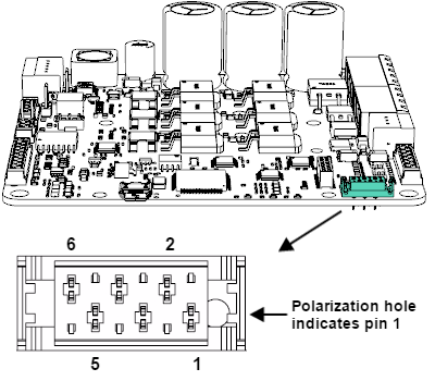
Absolute encoder connector
| P5 Connector | ||
|---|---|---|
6 pin TE Micro-Match 338068-6 connector. | ||
Pin | Signal | Function |
1 | +5V_OUT | +5V 200mA max supply for absolute encoder (shared with feedback and I/O connector) |
2 | GND | Ground connection |
3 | CLK+ | Absolute encoder CLK positive signal output |
| 4 | CLK- | Absolute encoder CLK negative signal output |
| 5 | DATA+ | Absolute encoder DATA positive signal input |
| 6 | DATA- | Absolute encoder DATA negative signal input |
| Notes | ||
| ||
| Ribbon cable mating | |
|---|---|
| Description | TE Micro-Match Male-on-Wire 1.27 mm pitch 6 position |
| Part number | |
Distributor codes | Digi-Key A99463CT-ND Mouser 571-7-215083-6 |
| Cable | |
| Part number | |
Distributor codes | Farnell 1859550 Digi-Key MD06R-100-ND Mouser 517-HF365/06SF |
| Multi-core crimped cable mating | |
|---|---|
| Description | TE Micro-Match housing connector 1.27 mm pitch 6 position |
| Part number | |
Distributor codes | Digi-Key A99415-ND Mouser 571-338095-8 |
| Cable | |
Use 0.2 ~ 0.5 mm² (20 ~24 AWG) flexible cable. | |
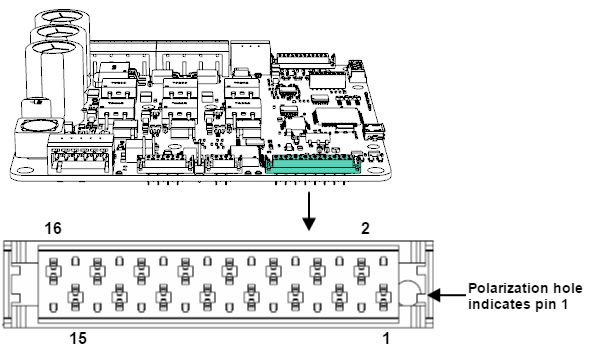
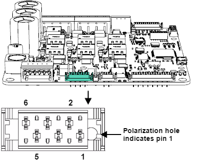
I/O connector
| P6 Connector | ||
|---|---|---|
16 pin 1.27 mm pitch TE Micro-Match 1-338068-6 connector. | ||
Pin | Signal | Function |
1 | HS_GPI2+ / DIR+ | High speed digital differential input 2+ |
2 | HS_GPI2- / DIR- | High speed digital differential input 2- |
3 | GND | Ground |
4 | GPO2 | Digital output 2 (open collector with weak pull-up to 5 V) |
5 | GPO1 | Digital output 1 (open collector with weak pull-up to 5 V) |
6 | GND | Ground |
7 | HS_GPI1+ / PULSE+ / PWM+ | High speed digital differential input 1+ |
8 | HS_GPI1- / PULSE- / PWM- | High speed digital differential input 1- |
9 | GND | Ground |
10 | AN_IN1 | Single ended analog input 1 |
11 | AN_IN2- | Differential analog inverting input 2 |
12 | AN_IN2+ | Differential analog non inverting input 2 |
13 | GND | Ground |
14 | GPI2 | General purpose single ended digital input 2 |
15 | GPI1 | General purpose single ended digital input 1 |
16 | +5V_OUT | +5V 200mA max output (shared with feedback and absolute encoder connector) |
| Notes | ||
I/O Starter Kit and Cable Kit Feedback connector pinout is shared with Pluto, Hydra, Nix and Neptune servo drives, which allows using the IO starter kit and Pluto Cable Kit. | ||
| Ribbon cable mating | ||
|---|---|---|
| Description | TE Micro-Match Male-on-Wire 1.27 mm pitch 16 position | |
| Part number | ||
Distributor codes | Farnell 149147 Digi-Key A99458CT-ND Mouser 571-8-215083-6 | |
| Cable | ||
| Part number | ||
Distributor codes | Farnell 1369751 Digi-Key MC16M-300-ND Mouser 517-C3302/16SF | |
| Notes | ||
| ||
| Multi-core crimped cable mating | |
|---|---|
| Description | TE Micro-Match housing connector 1.27 mm pitch 16 position |
| Part number | |
Distributor codes | Digi-Key A99495-ND Mouser 571-1-338095-6 |
| Cable | |
Use 0.2 ~ 0.5 mm² (20 ~24 AWG) flexible wires. | |
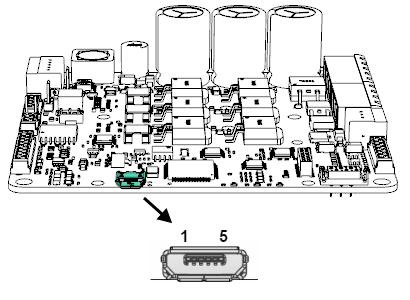
USB connector
| P7 Connector | ||
|---|---|---|
5 pin horizontal micro-USB connector Amphenol FCI 10118193 | ||
Pin | Signal | Function |
1 | USB_SUPPLY | USB +5 V supply input. Used to power logic circuits when no external power supply is available. |
2 | USB_D- | USB Data- line |
3 | USB_D+ | USB Data+ line |
4 | NC | Not connected |
5 | GND | Ground |
| SHIELD | NC | Connector metallic shield, NOT CONNECTED. |
| Notes | ||
| ||
| Mating | |
|---|---|
| Description | USB Shielded I/O Cable Assembly, USB A-to-Micro-USB B, 1.50m Length, Black, Lead-Free |
| Image | 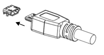 |
| Part number | |
Distributor codes | Farnell 1617586 Digi-Key WM17146-ND Mouser 538-68784-0002 |
CAN connector
| P8 Connector | ||
|---|---|---|
4 pin TE Micro-Match 338068-4 connector. | ||
Pin | Signal | Function |
1 | CAN_GND | CAN ground (isolated from Jupiter power GND) |
2 | CAN_L | CAN bus line dominant low |
3 | CAN_H | CAN bus line dominant high |
| 4 | CAN_GND | CAN ground (isolated from Jupiter power GND) |
| Notes | ||
| ||
| Ribbon cable mating | |
|---|---|
| Description | TE Micro-Match Male-on-Wire 1.27 mm pitch 4 position |
| Part number | |
Distributor codes | Farnell 2399655 Digi-Key A107032TR-ND Mouser 571-215083-4 |
| Cable | |
| Part number | |
Distributor codes | Farnell 2396432 Digi-Key MD04R-100-ND Mouser 517-HF365/04SF |
| Notes | |
Wire impendance Typical flat ribbon cables with 1.27 mm pitch spacing have 90 Ω to 150 Ω differential impedance. For best CAN bus performance at high baud rates, the ribbon cable impedance should be ~120 Ω. | |
| Multi-core crimped cable mating | |
|---|---|
| Description | TE Micro-Match housing connector 1.27 mm pitch 16 position |
| Part number | |
Distributor codes | Farnell 2420421 Mouser 571-338095-4 |
| Cable | |
Use 0.2 ~ 0.5 mm² (20 ~24 AWG) twisted pair with 120 Ω differential impedance. | |
RS485 interface connector
Jupiter Servo Drive is provided with RS485 interface, but can be supplied with RS232 interface. Please, contact with Ingenia to purchase Jupiter Servo Drive with RS232.
| P9 Connector | ||
|---|---|---|
8 pin TE Connectivity 338068-8 connector. | ||
Pin | Signal | Function |
1 | RETURN_TX | Internally connected to pin 6. Used only to simplify daisy chain wiring. |
2 | GND | Common (internally connected to drive GND) |
3 | RX+ | RS485 receive data + (should be connected to master TX+) |
| 4 | RX- | RS485 receive data - (should be connected to master TX-) |
| 5 | GND | Common (internally connected to drive GND) |
6 | RETURN_TX | Internally connected to pin 2. Used only to simplify daisy chain wiring. |
| 7 | TX+ | RS485 transmit data + (should be connected to master RX+) |
| 8 | TX- | RS485 transmit data - (should be connected to master RX-) |
| Notes | ||
| ||
| Ribbon cable mating | |
|---|---|
| Description | TE Micro-Match Male-on-Wire 1.27 mm pitch 8 position |
| Part number | |
Distributor codes | Farnell 149184 Digi-Key A99462CT-ND Mouser 215083-8 |
| Cable | |
| Part number | |
Distributor codes | Farnell 1859550 Digi-Key MD06R-100-ND Mouser 517-HF365/06SF |
| Multi-core crimped cable mating | |
|---|---|
| Description | TE Micro-Match housing connector 1.27 mm pitch 8 position |
| Part number | |
Distributor codes | Digi-Key A99415-ND Mouser 571-338095-8 |
| Cable | |
Use 0.2 ~ 0.5 mm² (20 ~24 AWG) flexible cable. | |
RS232 interface connector
Jupiter Servo Drive is provided with RS485 interface, but can be supplied with RS232 interface. Please, contact with Ingenia to purchase Jupiter Servo Drive with RS232.
| P10 Connector | ||
|---|---|---|
6 pin TE Connectivity 338068-6 connector. | ||
Pin | Signal | Function |
1 | RETURN_TX | Internally connected to pin 6. Used only to simplify daisy chain wiring. |
2 | GND | Common (internally connected to drive GND) |
3 | RX | RS485 receive data (should be connected to master TX) |
| 4 | TX | RS485 transmit data (should be connected to master RX) |
| 5 | GND | Common (internally connected to drive GND) |
6 | RETURN_TX | Internally connected to pin 2. Used only to simplify daisy chain wiring. |
| Notes | ||
| ||
| Ribbon cable mating | |
|---|---|
| Description | TE Micro-Match Male-on-Wire 1.27 mm pitch 6 position |
| Part number | |
Distributor codes | Digi-Key A99463CT-ND Mouser 571-7-215083-6 |
| Cable | |
| Part number | |
Distributor codes | Farnell 1859550 Digi-Key MD06R-100-ND Mouser 517-HF365/06SF |
| Multi-core crimped cable mating | |
|---|---|
| Description | TE Micro-Match housing connector 1.27 mm pitch 6 position |
| Part number | |
Distributor codes | Digi-Key A99415-ND Mouser 571-338095-8 |
| Cable | |
Use 0.2 ~ 0.5 mm² (20 ~24 AWG) flexible cable. | |
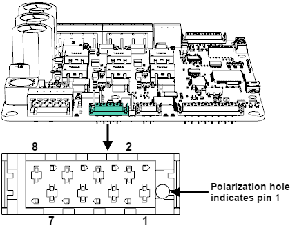
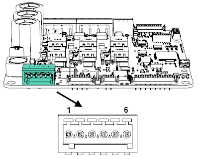
STO connector
| P11 Connector | ||
|---|---|---|
6 position 2.5 mm pitch pluggable terminal block. Phoenix Contact 1881480 | ||
Pin | Signal | Function |
1 | STO1+ | STO1 positive input |
2 | STO1- | STO1 negative input |
3 | STO2+ | STO2 positive input |
| 4 | STO2- | STO2 negative input |
| 5 | STO_SUP | Positive supply for STO (internally connected to drive +5V_OUT) |
| 6 | STO_GND | Negative supply for STO (internally connected to drive GND) |
| Notes | ||
| ||
| Mating | |
|---|---|
| Description | Pluggable terminal block, 6 positions 2.5 mm pitch |
| Part number | |
Distributor codes | Digi-Key 277-1434-ND Mouser 651-1881367 |
| Notes | |
| |
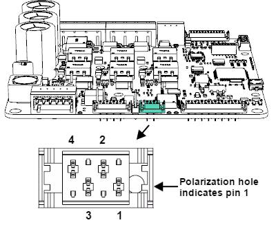
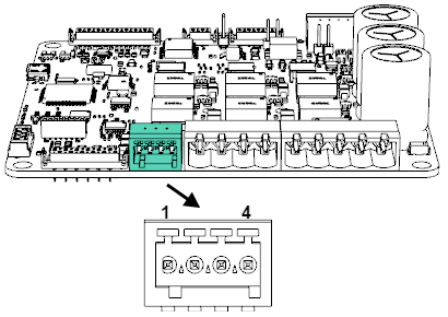
Motor safety connector
| P12 Connector | ||
|---|---|---|
4 position 2.5 mm pitch pluggable terminal block. Phoenix Contact 1881464 | ||
Pin | Signal | Function |
1 | EXT_TEMP | External temperature sensor input. Can be accessed internally as Analog input 3 (AN_IN3). |
2 | GND | Ground connection (for temperature sensor) |
3 | BRAKE- (GPO5) | Brake negative output. Open drain output controlled from GPO5, should be configured accordingly. |
| 4 | BRAKE+ (VBUS) | Brake positive output (Internally connected to the DC bus) |
| Notes | ||
| ||
| Mating | |
|---|---|
| Description | Pluggable terminal block, 4 positions 2.5 mm pitch |
| Part number | |
Distributor codes | Digi-Key 277-1432-ND Mouser 651-1881341 |
| Notes | |
| |
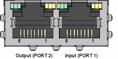
Connectors position and pinout of Jupiter with EtherCAT(JUP-x/xx-E)
EtherCAT connectors
| P7-P8 Connectors | ||
|---|---|---|
Pin | Signal | Function |
1 | TX_D+ | Transmit Data+ line |
2 | TX_D- | Transmit Data- line |
3 | RX_D+ | Receive Data+ line |
4 | +2V5 | 2.5 V generated internally |
5 | +2V5 | 2.5 V generated internally |
| 6 | RX_D- | Receive Data- line |
| 7 | NC | Not connected |
| 8 | GND_CHASSIS | Connected to the connector chassis |
| Notes | ||
| ||