
Introduction
Humanoid robots entail a large number of highly integrated joints and linkages (around 30 or even more, excluding the hands). This easily develops into a rather crowded electromagnetic environment where good wiring practices are paramount –even at the prototype stage– to prevent issues ranging from malfunction to certification flaws, which may even force the project roadmap to undertake major, unplanned redesigns.
Since every system is unique, and due to the complexity and heterogeneity of such robots, it’s barely feasible to establish rules of thumb that would apply to every case. It is possible, though, to describe a few recurrent solutions that apply to the more common architectures, as well as basic EMC advice that is generally valid in the context of robotics. These are by no means compulsory and should always be aligned with a Grounding Strategy that must be fully defined in advance.
Terminology
Throughout this document, the following wording applies:
-
DC bus: each one of the branches connected to the robot battery and distributing the Power supply to each one of the robot’s limbs (this is an assumed architecture; a different one may apply).
-
Battery Negative (–): also, VBAT-. lower potential terminal of the robot battery, hence the main low-driven reference voltage of the system.
-
GND_P: DC bus reference voltage, or reference voltage of the Power supply of the joint. Typically connected to the Battery negative, but not necessarily equipotential, since drop in the DC bus cables may happen at high or fast currents.
-
GND_D: reference voltage of the Logic supply. This can be provided externally to the drive (dual supply architecture), or generated internally in a DC/DC (single supply architecture). In either case, this is assumed to be the reference voltage used in feedbacks, digital I/Os, as well as non-isolated communications (if any).
-
PE: industrial terminology that stands for “Protective Earth”. In the context of this document, it is intended to be robustly connected to the joint or robot’s metal chassis.
-
Ethernet ground: also ECAT shield or ECAT chassis. Ethernet cables often use an STP (Shielded Twisted Pair) structure with the shield ending up in a metallic chassis of the RJ-45 connector from CAT 5e and supperior (this is usual, but not always true). Ethernet ground refers to said terminal.
DC bus topologies
As a common approach, humanoids tend to distribute supply in a star topology, the battery being the central node and the limbs being the DC bus branches. We are going to limit our focus here to one of these branches, for which we can foresee a typical population of 6 or 7 actuators, plus some sensors or end effectors.
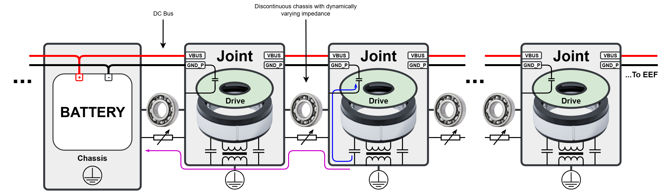
Inside each joint, the motor stator develops inductive and capacitive couplings towards the housing or chassis. While the phase currents resolve their differential components towards each other, the common-mode components, higher in harmonic content, must return to the bus reference. Higher frequencies (in the order of >100 MHz for GaN inverters) can get mostly resolved by including the proper decoupling capacitors inside the joint (often in the drive). But since the switching among the drives is generally not synchronized, low and mid-range frequencies are able to overcome the bus impedance and try to return to the lowest potential (typically the torso metal chassis around the battery) or bounce to each other.
This entails a problem, since the chassis of an articulated limb is not continuous all along the limb: bearings, slip rings and other mechanical elements change impedance dynamically, not to mention the presence of materials like carbon or glass fiber. Thus, the chassis may not suffice as an effective return path, leading to 2 major types of malfunctions:
-
Fast dV/dt voltages appearing between linkages, causing the chassis to radiate, and potentially inducing noise to any non-shielded sensitive signal moving across the limb.
-
Common Mode (CM) components finding lower impedance paths through comms (i.e. Ethernet shield), since is often the only other cable moving through linkages and thus contaminating them.
Common mitigating strategies
To overcome the previously mentioned issues, 2 common approaches are worth observing:
-
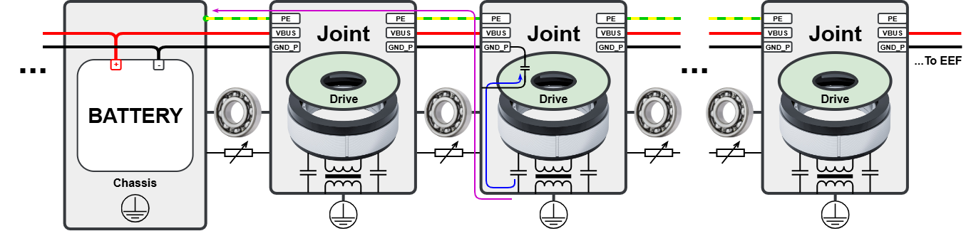
Providing a continuous, low-impedance PE/Chassis conductor to pipe the CM returns away from other sub-systems (recommended).
-
-
Pro: the chassis can be kept isolated from the DC bus, which may be beneficial for some grounding or certification strategies.
-
Pro: a priority path for CM returns keeps them away from sensitive sub-systems, even if they share a common supply.
-
Con: a 3rd thick conductor must be added to the DC bus, which may complicate the limb’s wiring, especially in hollow-shaft architectures.
-
-
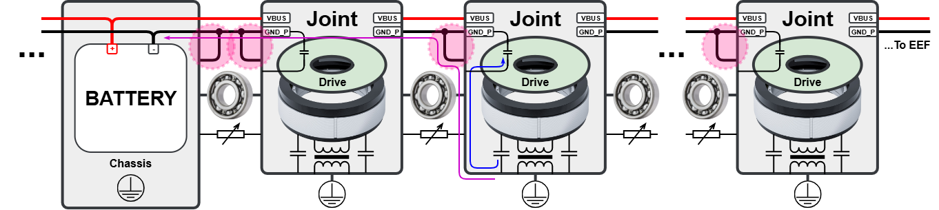
Tying the torso chassis to the negative terminal of the battery (–) to keep them equipotential, hence allowing the return of the CM components through the GND conductor. This is possible in most certification contexts, since conducted emissions EMI compliance is generally not requested in battery-powered systems. Now, the DC bus impedance is generally high enough to allow voltage drops between joints in mid-range frequencies, so the method must be complemented with short, thick ties from chassis to GND_P repeated at every joint.
-
-
Pro: the DC bus is still comprised of only 2 conductors.
-
Con: the chassis is no longer isolated, so this is not compatible with some certification frameworks.
-
Con: possible contamination of the DC bus reference. Filtering may be required to prevent affectation over sensitive sub-systems sharing the power supply.
-
The following sections expand on these propositions.
EMI model of a drive
The main source of electromagnetic noise in a servo drive is the high-frequency switching of the power stage. Gallium nitride transistors (GaN FETs), specifically, enable high efficiency, compact size, and high-power density. This comes at a cost, though, since their fast-switching voltages and current transitions can generate significant high-frequency disturbances when they interact with the parasitic capacitances and inductances of the drive, the motor, and the surrounding electromagnetic context. Careful system integration is therefore essential to control the associated current paths and prevent noise from coupling into sensitive circuits and communication interfaces.
The following sections use simplified electrical models to illustrate the main common-mode noise sources, coupling mechanisms, and return paths in a servo-drive system. Based on these models, practical grounding, bonding, shielding, and wiring measures are proposed to improve the EMC performance of the complete system.
Single Actuator Model
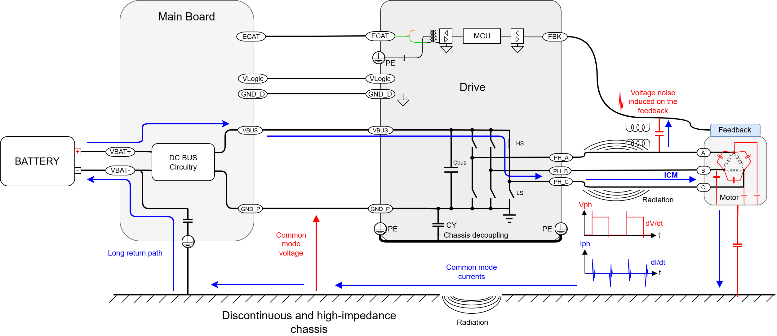
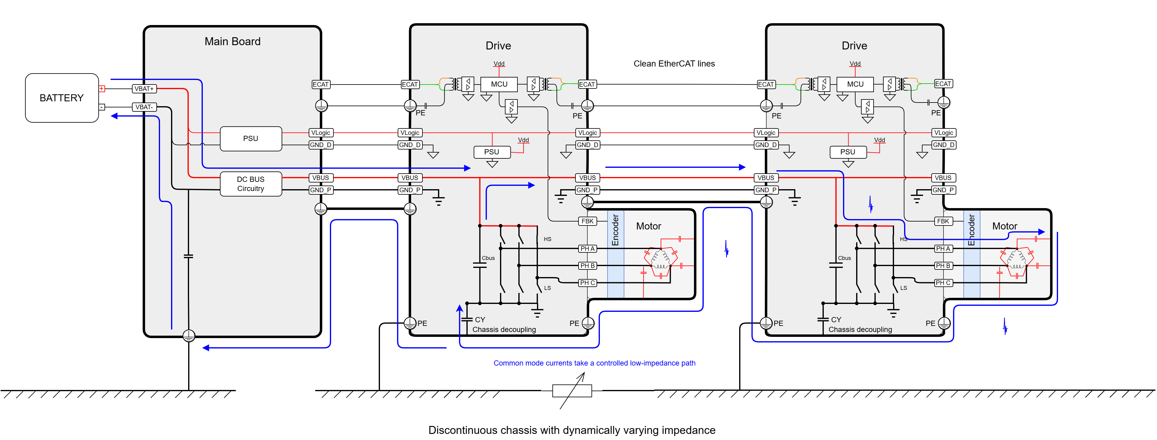
The next diagram shows the high-frequency EMC model of a drive without a proper low-impedance chassis path. Parasitic capacitances are shown in red, and CM current paths are shown in blue.
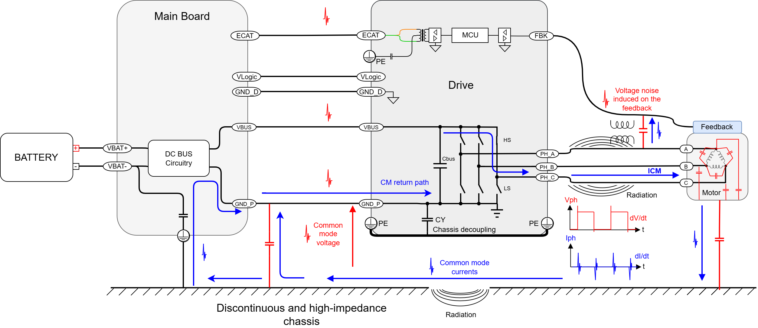
The fast voltage slopes generated by the drive’s power stage induce CM currents through the parasitic capacitances between the motor windings and the motor housing.
From the motor housing, this current must find a path back to the power stage capacitors. If the chassis path is discontinuous or has high impedance, the CM current is forced to return through longer, unintended paths. This high-frequency loop is typically the most critical and problematic because even small parasitic capacitances and inductances can significantly influence its impedance and determine how the current propagates through the system.
These unintended paths may involve the power reference, DC bus wiring, control electronics, feedback wiring, EtherCAT/Ethernet physical layer, and other parasitic couplings within the system. Their impedance creates CM voltage differences between different parts of the system. These voltage differences can couple noise into feedback and communication interfaces, increase radiated and conducted emissions, and raise the risk of communication errors or other EMC-related issues.
Similarly, there’s also a lower-frequency common mode component that has to return to the battery. Although these currents are generally less affected by small parasitic elements, their loops may extend across the complete system and include long cables, flex sections, connectors, and other conductors with significant inductance. The impedance of this extended path can produce significant CM voltage differences. These disturbances may couple into the drive electronics and communication interfaces, potentially affecting their operation. This battery return path is depicted hereafter:
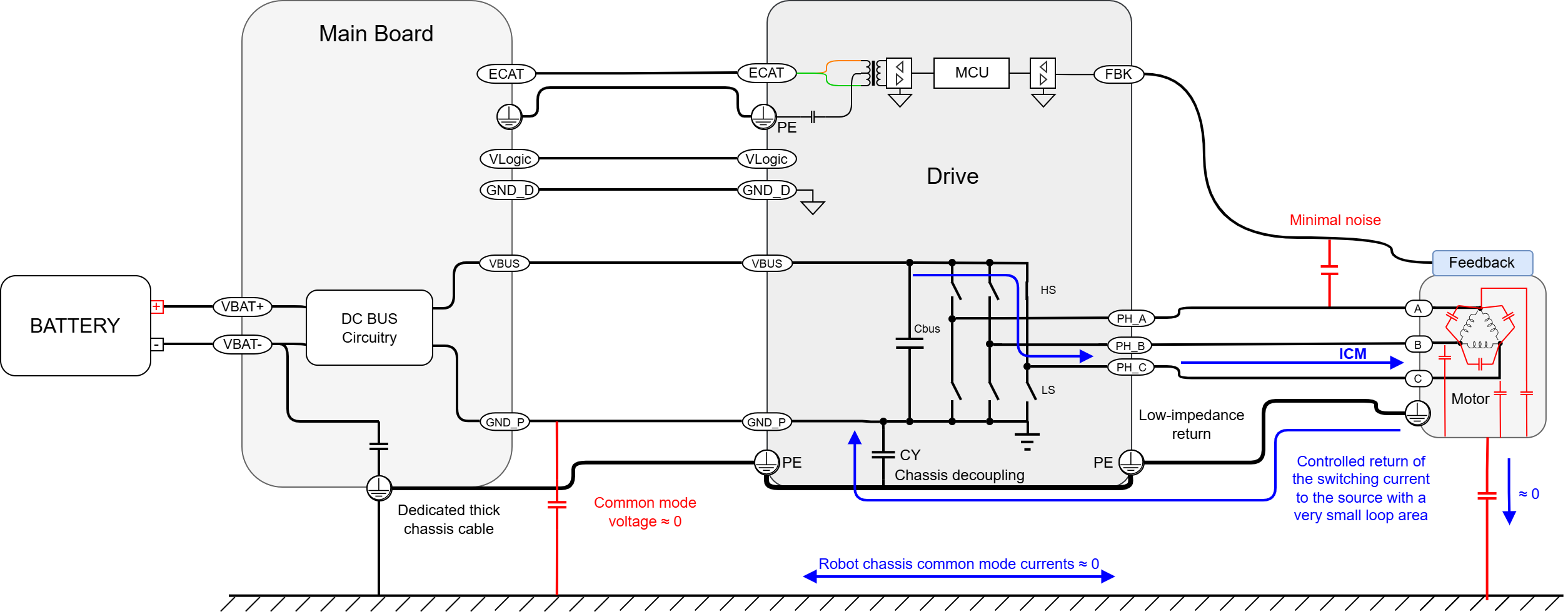
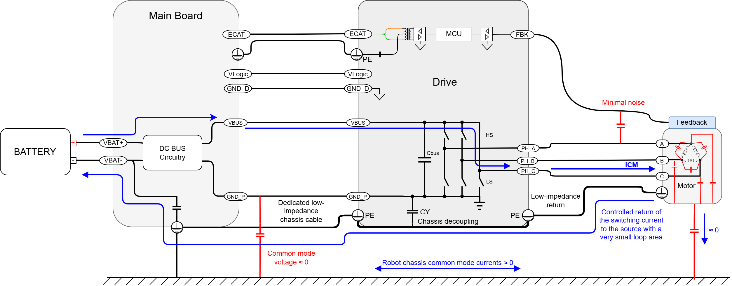
A highly effective way to address these issues is to provide a short, thick, and low-inductance chassis path between the motor housing and the drive chassis. This gives CM currents a controlled local path back to their source, rather than allowing them to flow through longer, unintended paths involving the power, feedback, or communication wiring.
Reducing the area and impedance of the common-mode loop limits the resulting CM voltage, reduces inductive voltage spikes and EMI coupling, and helps prevent noise from reaching the communications interface, feedback signals, and other sensitive electronics.
The following diagram illustrates the resulting high-frequency CM current path:
The effect on the lower-frequency CM currents is shown next:
Integrated Multi-Actuator Daisy Chain Model
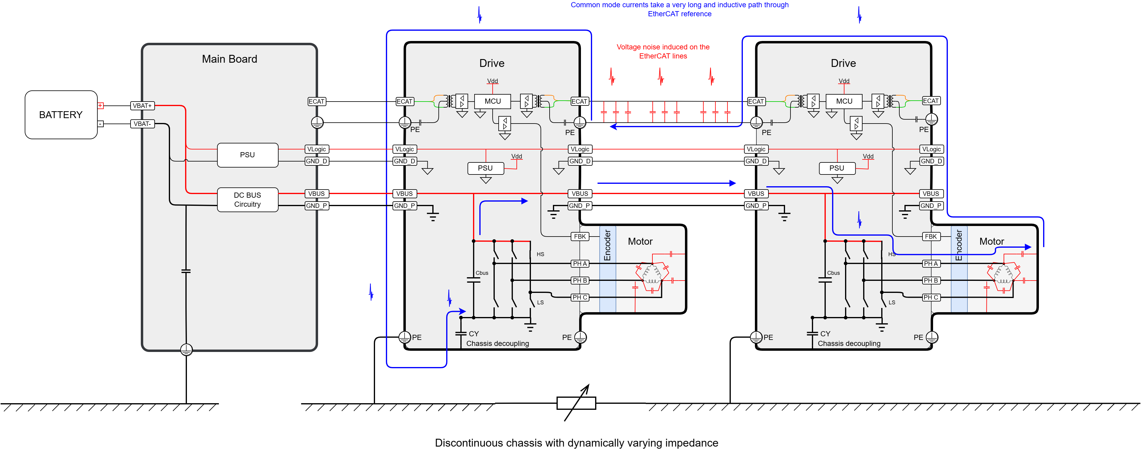
As it has already been introduced, some range of CM currents need to return to the power stage capacitors and others to the battery. However, in a multi-actuator limb, other more complex return paths start to appear. In particular, the DC bus behaves as a distributed capacitive network, meaning that some CM currents may also need to return to another axis rather than locally to the same actuator.
Therefore, the system must provide a thick, low-impedance, and uninterrupted chassis return path from actuator to actuator. If not provided, some CM currents can return only through unintended paths, such as the communications reference (often the cable shield, which is heavily capacitively coupled to the data conductors), causing significant interference to the communications, or even dropping the network completely. This problem becomes more severe as the number of actuators in the chain increases.
The diagram below illustrates this effect in a two-axis system:
The following diagram illustrates how proper integration strategies provide controlled return paths for both the high-frequency and lower-frequency CM currents:
Final set of recommendations
Handling of high-frequency CM currents
A decoupling capacitor is strongly recommended to provide a local return path for high-frequency common-mode currents. It should be connected between the motor chassis and GND_P and be placed as close as possible to the power stage or, if not accessible, to the drive power supply pins. X1/Y2-rated ceramic capacitors usually offer a good size-to-performance trade-off for SMT applications.
Check whether the drive already includes this capacitor, sometimes even several of them, and which terminals hold this connection (may not be all of the available ones marked as “PE” or “Chassis”).
Robot Chassis Termination
Battery-powered mobile systems can use either a directly referenced chassis or an isolated battery bus with a controlled high-frequency connection to chassis. The appropriate approach depends on the electrical safety concept, fault-detection requirements, insulation-monitoring strategy, and applicable system requirements.
Option 1: Direct connection to VBAT−
If battery-to-chassis isolation is not required, connect the chassis directly to VBAT− at a single, defined point close to the battery or main power-distribution unit. This connection:
-
Establishes a defined chassis potential.
-
Provides a controlled return path for CM current.
-
Allows a VBAT+ to chassis fault to produce sufficient current to operate the corresponding branch protection, provided that the protection is present.
-
The chassis must not be used as the normal load-current return. All intended DC load current should continue to flow through the dedicated VBAT+ and VBAT− conductors.
Option 2: Isolated battery bus with capacitive chassis coupling
If the battery bus must remain galvanically isolated from the chassis, controlled high-frequency return paths can be provided using capacitors between the battery bus and chassis.
For a symmetric configuration, connect equal-value capacitors from VBAT+ and VBAT− to chassis. This places the chassis approximately at the AC midpoint of the battery bus and provides balanced common-mode return impedances. A high-value resistor may also be added between chassis and a selected bus reference to prevent indefinite charge accumulation and provide a weak DC reference. However, this resistance creates a conductive path that must be considered when defining insulation-resistance monitoring thresholds.
Chassis bonding between actuators
A dedicated chassis bonding conductor should run from the main system chassis to every actuator housing and continue across the complete actuator chain. This connection provides a controlled return path for CM currents and prevents communication, feedback, or power-reference conductors from becoming unintended return paths. This document has already commented on the pros as cons of using the GND_P terminal of the DC bus for such purpose, or a dedicated conductor (preferred).
Long, narrow conductors may provide acceptable DC resistance but can have significant inductance and therefore high impedance at the relevant frequencies. Rapid changes in CM current flowing through this inductive path can produce substantial transient voltage differences between different parts of the chassis. For this reason, the chassis bonding path should be:
-
Continuous from the main system chassis to every actuator
-
Short and thick wherever mechanically possible
-
Designed for low impedance and, particularly, low inductance
-
Routed close to the power conductors to minimize the area of the common-mode loop
Clock springs and long flex sections can introduce significant inductance into the chassis path. Therefore, the chassis conductor through these sections should use the thickest/widest practical geometry and should not contain narrow necks, long pigtails, or unnecessary loops. Slip rings can introduce dynamic discontinuities of this bonding, so they are not recommended.
At each actuator, the chassis conductor should be bonded directly to the actuator housing. The connector mounting holes should be used for this purpose as they provide a reliable conductive connection. Paint, anodization, adhesives, contamination, and mechanical tolerances must not compromise the bond.
All the structural metal parts of the joint or linkage should be electrically connected together. Floating metal pieces, like heatsinks or metal flanges are easily driven into close-field voltages, potentially becoming “channels” for EMI contamination.
Ethernet/ EtherCAT shielding (100Base-Tx)
The preferred Ethernet shield termination depends on how chassis bonding is implemented and on the common-mode current paths present in the complete system.
In systems with a dedicated chassis-bonding cable running along the robot, the Ethernet cable shield may be connected to GND_P rather than to chassis. Due to its potential length, the chassis-bonding cable may present relatively high impedance at high frequencies while carrying significant return currents. Connecting the Ethernet shield to chassis could therefore create a lower-impedance parallel path, causing part of the high-frequency chassis current to flow through the shield and potentially disturb communications.
Where GND_P, and therefore the battery negative, is robustly bonded to the torso or battery chassis, two general cases can be considered:
-
The Master does not provide a chassis connection for the cable shield, for example because it has a plastic enclosure.
In this case, it is recommended to keep the Ethernet shields unconnected to anything but the Ethernet ground, which is assumed to be AC and even DC-decoupled from the Bob Smith termination.
-
The Master connects the cable shield directly to the torso or battery chassis.
In this case, connecting the shield at each joint to the local chassis or to the drive’s PE/chassis terminal will generally provide the most direct continuation of the shield path.
However, since real-world performance can be affected by many other factors, it is advised to retain the option to connect the Ethernet shields to either of the 3 options:
-
Joint’s chassis
-
GND_P
-
Ethernet ground (disconnected)
These options should be implemented using short, low-inductance connections. Long jumper wires or pigtails would be ineffective at high frequencies.
The Ethernet shield should form a continuous, low-impedance path and be terminated at both ends. While a single-ended shield may provide some reduction of electric-field coupling, effective attenuation of high-frequency common-mode noise and magnetically induced interference requires shield currents to flow continuously through the shield. This is only possible when the shield provides an uninterrupted low-impedance path across the relevant frequency range.
GND_D should not be used as a cable-shield termination or as a common-mode return conductor. GND_D is the reference for sensitive digital and control electronics, and diverting noise through it can create voltage disturbances directly at these circuits.
GND_D and GND_P should be treated as separate conductors externally, although within the drive they are often locally connected only at specific points where a shared reference is required, and in a controlled manner.