
What is the Safety widget?
This widget groups all aspects of FSoE and safety-related content of the connected drive; allowing to perform all safety related configurations.

It contains the following parts:
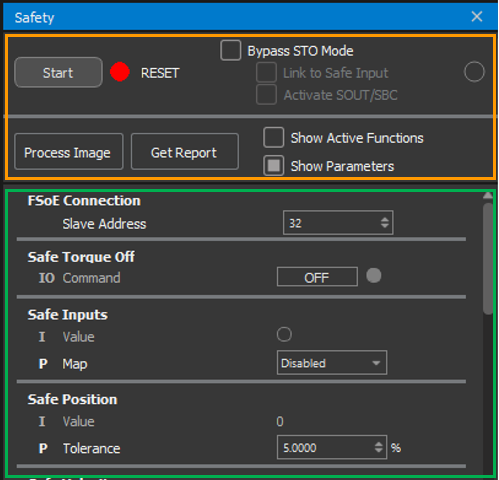
Top menu (orange rectangle above):
Divided into two main sections.
-
Upper section:
State/Mode controls.
-
Start/Stop Master Control button: Transitions the state of the FSoE Master from Start to Stop and vice versa.
-
State Master Display: Displays the current FSoE Master state
(


-
Bypass STO Mode: Checkbox to enable STO Mode. When selected, a special Safety Master is loaded that only configures and releases STO. (Learn more about STO Mode).
-
Error Display: LED blinks to indicate FSoE Errors. These errors can also be seen in the error bar.
-
-
Lower section:
Contains map-related configurations.
-
Process Image button: Opens the Process Image Editor, where available safety functions can be mapped. (Learn more about the Process Image Editor).
-
Get Report button: Opens the Report window, displaying all required configuration details (Process Data, Safety Parameters, CRC, etc.). (Learn more about the Report).
-
Group filters:
Options to show/hide elements in the Groups section.-
Show Active functions: Displays only active safety functions when checked (this includes mapped functions, and functions that are activated by others.).
-
Show Parameters: Displays parameters when checked; hides them when unchecked.
-
-
Groups (green rectangle below):
Displays all available safety fields (IOs and Parameters) grouped by safety function. Includes additional safety parameters and configurable settings such as the FSoE Connection - Slave Address.
Configuring and working with Safety
Bypass STO Mode
Warning: This setting bypasses the configured Safety Master and disables all Safety Functions except STO. Use at your own risk!
When enabled, this mode:
-
Overrides the existing Safety Master with a configuration that only maps the STO function.
-
When Safety Master is Started, the STO is always released.
This setting can only be modified when the Safety Master is Stopped.
How to enable the Bypass STO Mode:
-
Click on Bypass STO Mode.
-
(Optional) Additional options (only available when Bypass STO Mode is selected):
-
Link to Safe Input to trigger STO through the Safe Input. An emergency switch can be added to your setup and connected to this Input, triggering STO when activated.
-
Activate SOUT/SBC to also deactivate the SOUT/SBC upon STO release (only available on certain drives).
-
-
Click on Start to activate the bypass.
When disabled, the Safety Master is rolled back to the previously configured Safety Master.
Process Image
This pop-up window allows to modify mapped Input and Output safety functions.
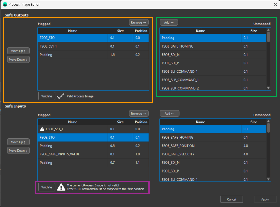
Unmapped table (green box):
Displays all available safety functions not yet mapped.
To map a function:
-
Select the desired function in the Unmapped table.
-
Click Add.
-
(Optional) Add Padding following the same steps.
Mapped table (orange box):
Displays all currently mapped safety functions.
To adjust the order:
-
Select the function in the Mapped table.
-
Click Move Up / Move Down.
To modify the size of the padding:
-
Select the padding in the Mapped table.
-
Click on the Size box and input a new value.
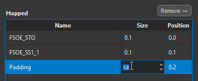
Validation (purple box):
Before applying changes, both Input and Output Mapped images must be validated.
To validate:
-
Click Validate.
-
If validation fails or is incomplete:
-
The map is invalid and cannot be applied.
-
Modify map and try again.
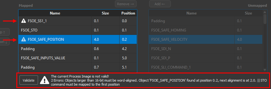
Example of invalid map. Errors are marked on the Mapped table with a more detailer explanation below.
-
Apply:
To apply changes:
-
Click Apply once both maps are valid.
Apply button remains disabled until both images are valid.
Get Report
This pop-up window provides all configuration details required by the Safety Master. Use this information as a reference when configuring the Safety Master, but always verify these details against the Products' Safety Manual.
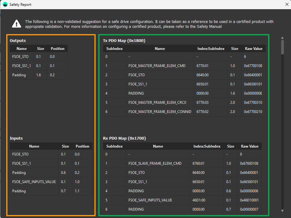
Outputs and Inputs (orange box):
Displays mapped Input and Output functions, including Size and Position.
TxPDO Map and RxPDO Map (green box):
Contains the Rx and Tx PDO map, with their Index:SubIndex, Size and Raw Value.
It also includes the FSoE Command, FSoE CRC, and Truncated 32 bit elements.
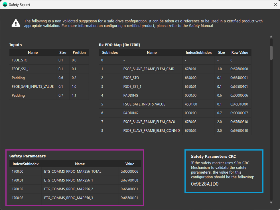
Safety Parameters (purple box):
Lists all safety parameters with their Index:SubIndex and Value.
Safety Parameters CRC (blue box):
Displays the CRC for the configured Safety Parameters.
Groups
Contains all safety-related fields (IOs, Safety Parameters, and other settings), grouped by safety function or other functionalities.
-
Safety IOs: Values can be viewed and toggled.
-
Safety Parameters: Values can be modified.
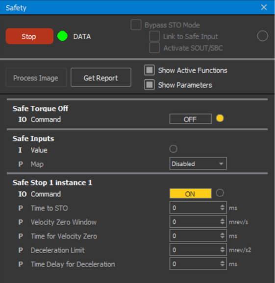
Groups get hidden when Bypass STO Mode is enabled.
Functionalities
|
IOs items |
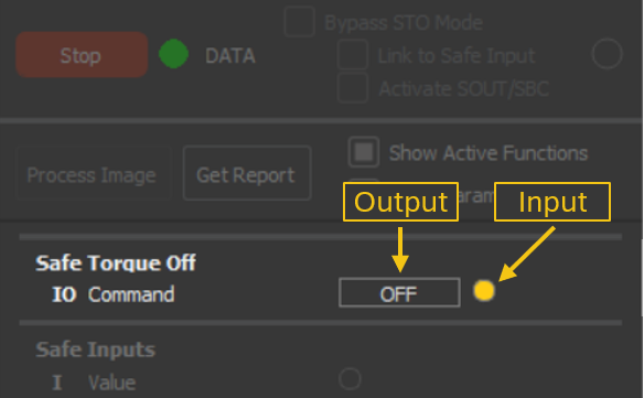
|
|
|
Input items |
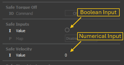
|
|
|
Parameters |
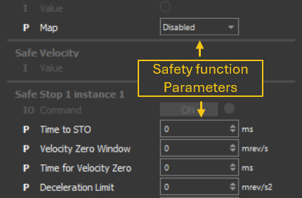
|
|
Filters
Groups can be filtered at any time:
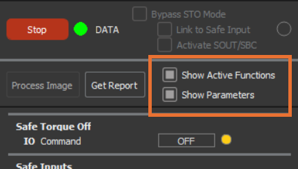
Show Active functions:
Displays only active safety functions when checked.
Beware that safety functions can be unmapped but active, due to dependencies.
Show Parameters:
Displays parameters when checked; hides them when unchecked.