How to Configure Different Absolute Encoder Feedback Setups
This article is based on Summit Drive Firmware 2.10.0 and MotionLab3 Version 1.10.0. Labels and GUI might defer depending on user firmware and software versions.
Supported Absolute Encoder Protocols
BiSS-C
BiSS-C is a serial protocol that offers a series of advantages when compared to other encoder protocols. These advantages include:
Standard product definition
Error, warning, and provided CRC checking
Allows for daisy chain operation
Below is an example of a more common BiSS-C frame structure (BP1/BP3) to outline some of the key bits of information that need to be pulled to configure the encoder properly in MotionLab3 or directly through the summit registers.
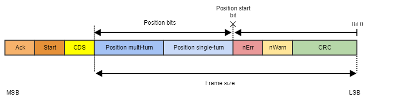
Representative BP1/BP3 BiSS-C Frame Structure
The BiSS-C protocol supports a number of multi-encoder configurations including:
Diasy chain operation
Multiple BiSS-C positions in the same frame
These configurations will be described in more detail below.
SSI
SSI is also a serial protocol but does not have a specific frame structure so configuration can vary from manufacturer to manufacturer. Some of these protocols have manufacturer-specific special bits that may or may not be supported by the drive. This is accounted for by setting the 0x2374 - Primary Absolute Slave 1 - Frame type, 0x237C - Secondary Absolute Slave 1 - Frame type parameter in the software configuration.
Below is an example of a generic SSI frame to help highlight how to decipher the important information needed to configure the encoder.
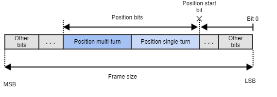
Representative Generic SSI Frame Structure
EnDAT 2.2
EnDat 2.2 support is only available in EVS-NET and CAP-NET drives.
EnDAT 2.2 is a proprietary serial protocol that manages both multi-turn and single-turn devices. The frame parsing is configurable allowing it to support a wide range of absolute encoder devices. This protocol offers a series of advantages. Among them are:
Standard protocol definition
Error and Warning bits. As well as CRC checking
It allows for bidirectional communication
There are many different frame structures within EnDAT 2.2 protocol, our drives support the most basic one described below.
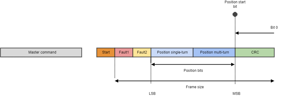
EnDAT 2.2 Frame Structure supported by Novanta Drives
Actuator Configurations
Single Absolute Encoder
Connection Diagram
A single absolute encoder connection is supported by either encoder input slot. This connection will vary depending on drive and form factor you are connecting to, please consult the corresponding product manual for your drive to ensure proper wiring connections.
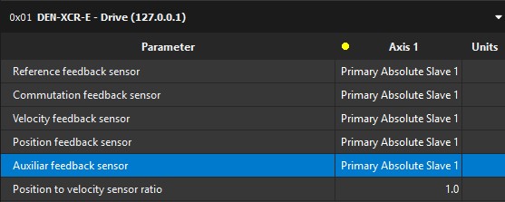
Motion Lab3 Configuration
For an application using just a single absolute encoder all the feedback slots should be set to Primary Absolute Encoder. If the encoder is wired to the secondary encoder pins on the drive please use the Secondary Absolute Encoder option. The feedback option is tied directly to the where the encoder is wired on the drive.
Single Absolute Encoder & Gearbox
It is mandatory that the encoder in this actuator be mounted to the motor. If it is not, the drive will not be able to properly commutate the motor.
Connection Diagram
A single absolute encoder connection is supported by either encoder input slot. This connection will vary depending on drive and form factor you are connecting to, please consult the corresponding product manual for your drive to ensure proper wiring connections.
Motion Lab3 Configuration
For an application using just a single absolute encoder all the feedback slots should be set to Primary Absolute Encoder, if wired to the Primary Absolute Encoder 1 slot.
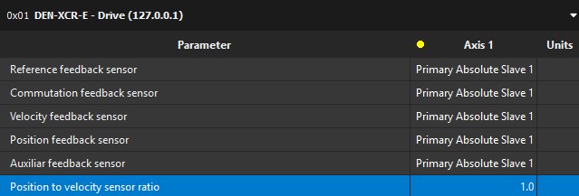
From there the encoder will need to be configured based on the frame structure it uses. With this type of actuator configuration please be aware that the drive has no register that accommodates for the gear ratio in this type of configuration. The 0x2364 - Position to velocity sensor ratio register only accommodates for the ratio between separate feedback devices so you will have to accommodate for the gear ratio in a higher-level motion controller, PLC, or program.
Primary and Secondary Encoders with a Gearbox
Connection Diagram
A dual absolute encoder connection is supported by either encoder input slot. If you are looking to use two encoders via daisy chain topology the first encoder will have to be connected to the absolute encoder 1 pins. These connections will vary depending on drive and form factor you are connecting to, please consult the corresponding product manual for your drive to ensure proper wiring connections. Please note which encoder is connected to which feedback slot this will be important later when configuring the drive.
Motion Lab3 Configuration
For an application using two feedback one on the motor and another on the output of the gearbox, the drive should be configured similar to the drive below.
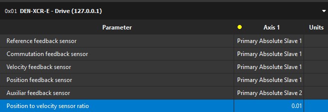
This is only one of multiple configurations for this type of actuator, but it should be noted that only the position feedback sensor is adjusted to accommodate for the gear ratio. The 0x2364 - Position to velocity sensor ratio register is used to accommodate for the gear ratio between the encoder used on the motor and the encoder used on the output of the gearbox. In this example a 100:1 gearbox is being used. This means that for every 1 revolution of the position feedback encoder the velocity feedback will move 100 revolutions resulting in a sensor ratio of 1 [rev] / 100 [rev] or 0.01.
Dual Absolute Encoders with a Gearbox, One Encoder is Only Used for Redundancy (Non-Safe Drives)
Connection Diagram
A dual absolute encoder connection can be connected in many different configurations. If you are looking to use two encoders via daisy chain topology the first encoder will have to be connected to the absolute encoder 1 pins. These connections will vary depending on drive and form factor you are connecting to, please consult the corresponding product manual for your drive to ensure proper wiring connections. Please note which encoder is connected to which feedback slot this will be important later when configuring the drive.
Motion Lab3 Configuration
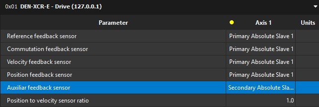
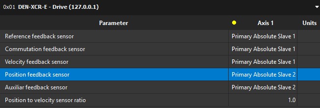
For an application using two feedback sensors but one of the encoders is only used for redundancy. The drive should be configured similar to the drive below, though this might vary depending on how the feedbacks are connected to the drive. For instance a daisy chain configuration will be use Absolute Slave 2 instead of Secondary Absolute Slave 1.
Two BiSS-C Encoders in Daisy Chain
Connection Diagram
Daisy chain connections is only supported via the absolute encoder 1 slot. This connection will vary depending on drive and form factor you are connecting to, please consult the corresponding product manual for your drive to ensure proper wiring connections.
Motion Lab3 Configuration
For an application using two BiSS-C encoders in a daisy chain configuration you leverage the “Primary Absolute Encoder 1” and “Primary Absolute Encoder 2” slots in the feedback’s menu. Below is an example of potential configuration.
When using daisy chain, the total frame size is made up of the start and CDS bits plus the Primary Absolute Slave 1 encoder frame size and Primary Absolute Slave 2 frame size combined. This combination must fit the maximum frame size of 64bits
From there you will need to configure each feedback based on how they have their data frame structured. Here is a representative daisy chain data frame configuration.
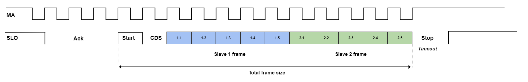
BiSS-C Diasy Chain Encoder Data Fram Structure
The one parameter that is important for daisy chain is the 0x2395 - Primary Absolute Feedback - Topology register. Setting this register to 2 or “Two BiSS-C feedbacks in daisy-chain” will ensure that the drive reads both encoders. A sample configuration of Primary Absolute Encoder 1 and 2 are below.
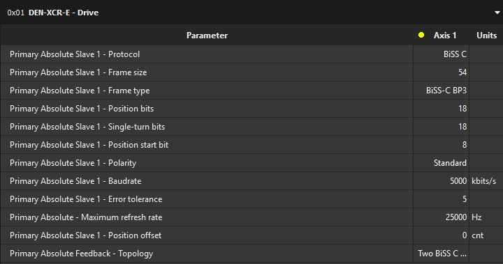
Primary Absolute Encoder 1
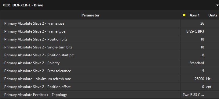
Primary Absolute Encoder 2
In this example we are daisy-chaining two 18-bit single turn absolute encoders that have BiSS-C BP3 frame formatting.
Two Biss-C Encoder Positions in the Same Frame (Dual Position BiSS-C Frame)
Connection Diagram
Dual BiSS-C operation connection is only support via the absolute encoder 1 slot. This connection will vary depending on drive and form factor you are connecting to, please consult the corresponding product manual for your drive to ensure proper wiring connections.
Motion Lab3 Configuration
For an application using dual BiSS-C configuration you leverage the “Primary Absolute Encoder 1” and “Primary Absolute Encoder 2” slots in the feedback’s menu. Below is an example of potential configuration.
From there you will need to configure each feedback based on how they have their data frame is structured. Here is a representative dual BiSS-C data frame configuration that we will use as an example.
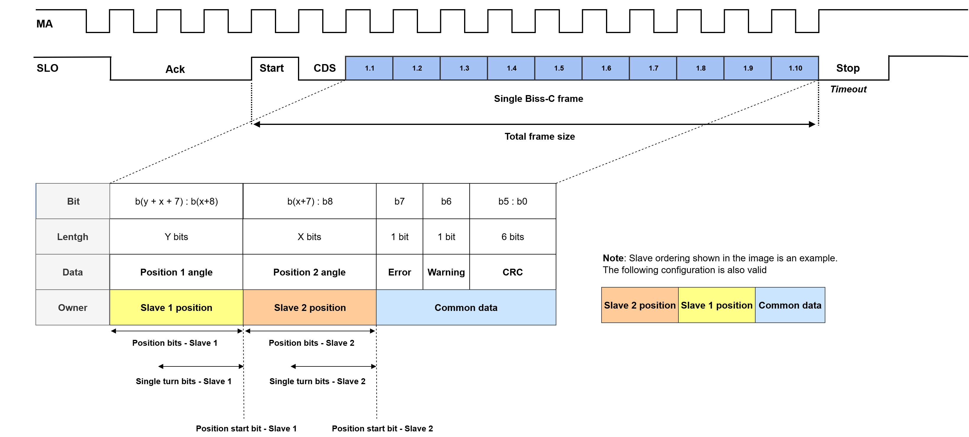
As with the diasy chain configuration you will have to set the topology register correctly to enable this operation. Setting this register to 20 or “Dual BiSS-C” will ensure that the drive reads both position frames. A sample configuration of Primary Absolute Encoder 1 and 2 are below. Again the 64-Bit frame limit is applicable.
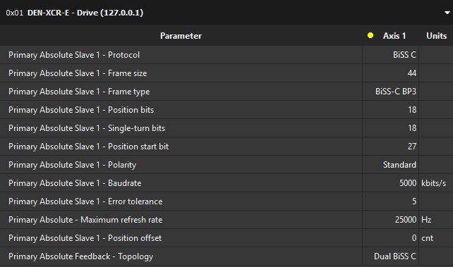
Primary Absolute Encoder 1
Again for this example we assumed the encoder had two 18-bit single turn position feedback in it.
The following registers of the Primary Absolute feedback - Slave 1 and Primary Absolute feedback - Slave 2 must share the same configuration:
Protocol
Frame size
Frame type
Polarity
To correctly parse the frames, the following parameters must be configured correctly and independently for each slave
Position bits
Single-turn bits
Position start bit