XCR Cable kit - Product Manual
Introduction
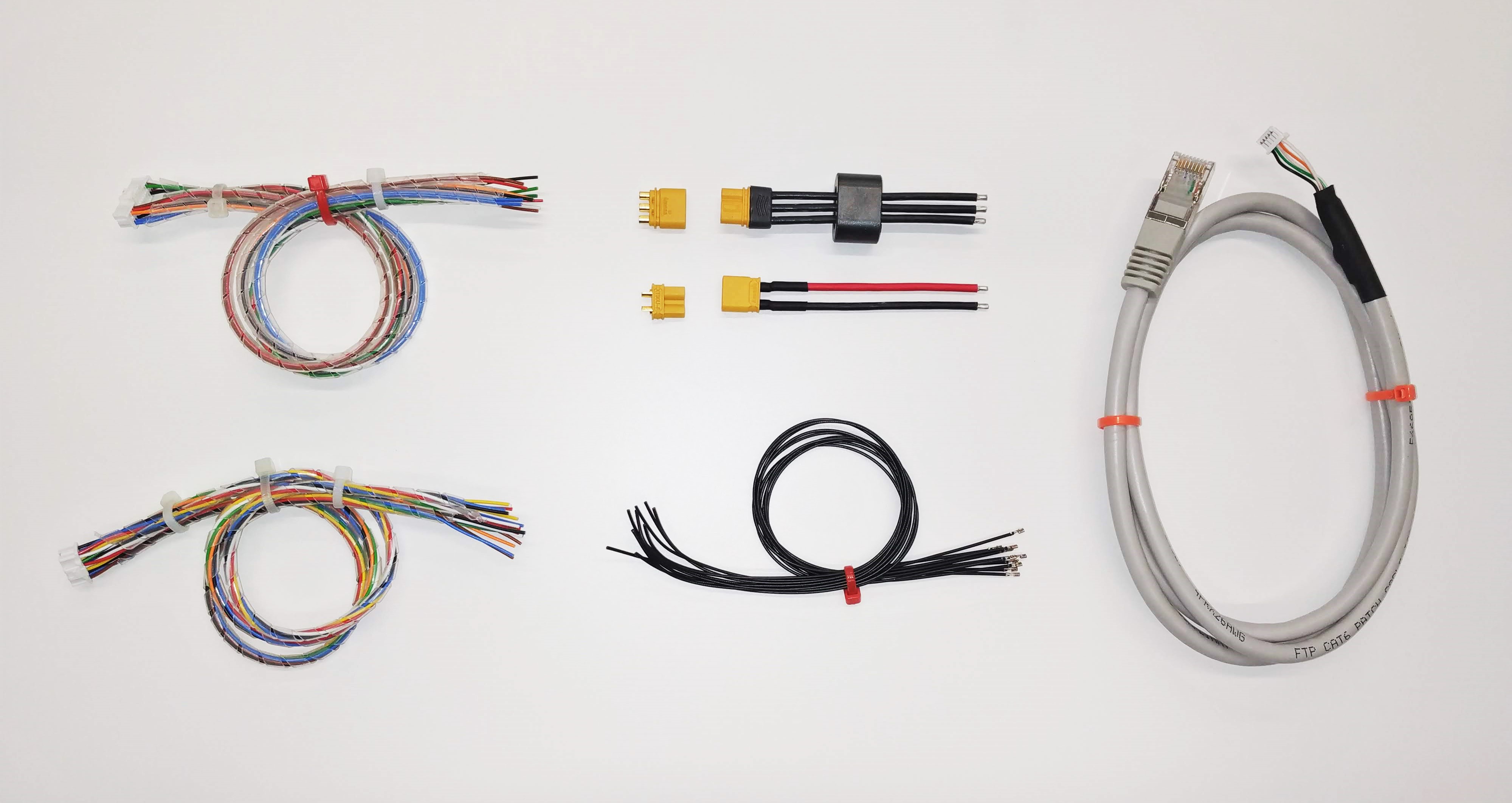
This document explains the content and wiring details of the XCR Cable Kit (XCR-CAB). The kit is provided as a tool to speed up the connection between Everest / Capitan XCR and the user's application.
It is composed of the following components:
- 1 x Power Supply cable - 60 mm (C-PC-PSU)
- 1 x Power Supply connector
- 1 x Motor Supply cable - 60 mm (C-PC-CO)
- 1 x Motor Supply connector
- 1 x EtherCAT Communication cable - 1 m (C-PC-ECAT)
- 1 x Feedback cable - 250 mm (C-PC-FEED)
- 1 x Input / Output cable - 250 mm (C-PC-IO)
- 10 x Extra Wires for Feedback & Input / Outputs - 250 mm (C-PC-EXTRA)
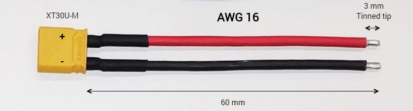
Power Supply Cable (C-PC-PSU)
The Power Supply cable is provided with a length of 60 mm. It consists of two AWG16 - 1.5 mm2 cables with an XT30U-M male connector from AMASS on one side and flying leads on the other side.
Flying leads should be soldered properly into the XCR P1 connector. Please, follow indications provided in the 'Soldering Power Pins' section in the product manual for your specific drive type for a proper assembly.
The pinout of the Power Supply Cable is as follows:
| Side 1 - pin | Side 2 - pin | Wire color | Signal | Function |
|---|---|---|---|---|
| 1 (+ Mark) | Flying lead | Red | POW_SUP | Power supply positive |
| 2 | Flying lead | Black | GND_P | Power supply return |
Diagram
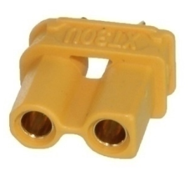
Power Supply Connector
The Power Supply matching connector for C-PC-PSU is also provided. It consists of an XT30U-F female connector from AMASS.
Recommended section wire is 2.5 mm2 ~ 5.3 mm2, AWG 10 ~ AWG 13 for applications working at maximum current. Adapt the cable diameter to your current needs.
It is recommended to use flexible silicone cables to ensure low mechanical stress to the board as well as high-temperature ratings (≥ 110 ºC).
Please, follow indications provided in the 'Cable Selection' and 'Power Supply EMI Filter' sections in the product manual for your specific drive type for a proper cable selection.
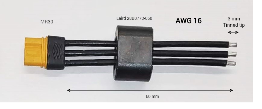
Motor Power Cable (C-PC-MO)
The Motor Power cable is provided with a length of 60 mm. It consists of three AWG16 - 1.5 mm2 cables with an MR30 female connector from AMASS on one side and flying leads on the other. A common mode choke model Laird 28B0773-050 is provided to simplify the installation where electromagnetic compatibility is needed. Flying leads should be soldered properly into the XCR P2 connector. Please, follow indications provided in the 'Soldering Power Pins' section in the product manual for your specific drive type for a proper assembly.
The pinout of the Power Supply Cable is as follows:
| Side 1 - pin | Side 2 - pin | Wire color | Signal | Function |
|---|---|---|---|---|
| 1 | Flying lead | Black | PH_A | Motor phase A |
| 2 | Flying lead | Black | PH_B | Motor phase B |
| 3 | Flying lead | Black | PH_C | Motor phase C |
Diagram
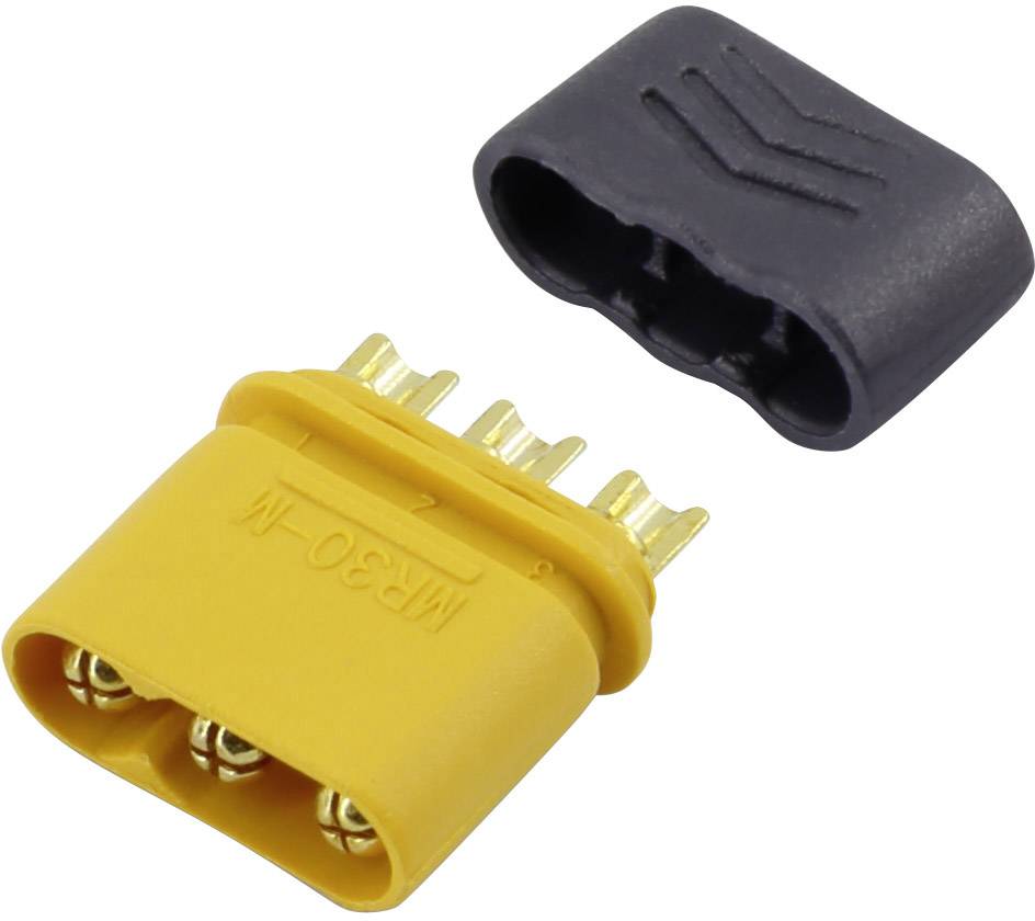
Motor Power Connector
The Motor Power matching connector for C-PC-MO is also provided. It consists of an MR30 male connector from AMASS.
Recommended section wire is 2.5 mm2 ~ 5.3 mm2, AWG 10 ~ AWG 13 for applications working at maximum current. Adapt the cable diameter to your current needs.
It is recommended to use flexible silicone cables to ensure low mechanical stress to the board as well as high-temperature ratings (≥ 110 ºC).
Please, follow indications provided in the 'Cable Selection' and 'Power Supply EMI Filter' sections in the product manual for your specific drive type for a proper cable selection
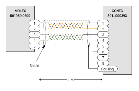
EtherCAT Communication Cable (C-PC-ECAT)
The EtherCAT Communication Cable is provided with a length of 1 m. It consists of a CAT6 (28 AWG - twisted pair & shielded) cable with a shielded RJ45 connector on one side and a 5-pin Molex Pico-clasp on the other. Molex Pico-clasp connector should be plugged directly into the XCR J4 connector.
The pinout of the EtherCAT Communication cable is as follows:
| Side 1 - pin | Side 2 - pin | Wire color | Twisted | Signal | Function |
|---|---|---|---|---|---|
| 1 | 1 | White - Orange | TX_D | TX_D+ | Transmit Data+ line |
| 2 | 2 | Orange | TX_D- | Transmit Data- line | |
| 3 | 3 | White - Green | RX_D | RX_D+ | Receive Data+ line |
| 4 | 6 | Green | RX_D- | Receive Data- line | |
| 5 | Connector shell | Drain wire | - | GND_ETH | Connection for the EtherCAT cable shield. This pin is directly connected to the chassis of the drive - PE. |
Diagram
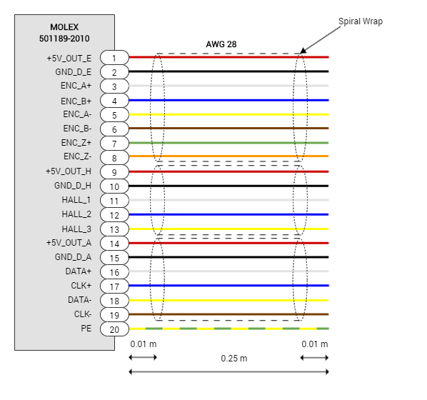
Feedback Cable (C-PC-FEED)
The Feedback cable is provided with a length of 250 m. It consists of a set of 15 x 28 AWG cables with a 20-pin Molex Pico-clasp connector on one side and flying leads on the other. Molex Pico-clasp connector should be plugged directly into the XCR J4 connector.
The cables are tie by means of spiral wraps in 3 different groups to simplify its identification:
- Digital Incremental Encoder
- Digital Halls
- Absolute Encoder
The pinout of the Feedback cable is as follows:
Side 1 - pin | Side 2 - pin | Wire color | Part Number | Signal / Label | Function |
|---|---|---|---|---|---|
| 1 | Flying lead | Red | 6820 RD005 | +5V_OUT_E | 5 V 200 mA total max. Differential digital incremental encoder group. |
| 2 | Flying lead | Black | 6820 BK005 | GND_D_E | Digital signal ground. Differential digital incremental encoder group. |
| 3 | Flying lead | White | 6820 WH005 | ENC_A+ | Differential digital incremental encoder: A+ input |
| 4 | Flying lead | Blue | 6820 BL005 | ENC_B+ | Differential digital incremental encoder: B+ input |
| 5 | Flying lead | Yellow | 6820 YL005 | ENC_A- | Differential digital incremental encoder: A- input |
| 6 | Flying lead | Brown | 6820 BR005 | ENC_B- | Differential digital incremental encoder: B- input |
| 7 | Flying lead | Green | 6820 GR005 | ENC_Z+ | Differential digital incremental encoder: Index+ input |
| 8 | Flying lead | Orange | 6820 OR005 | ENC_Z- | Differential digital incremental encoder: Index- input |
| 9 | Flying lead | Red | 6820 RD005 | +5V_OUT_H | 5 V 200 mA total max. Digital hall group. |
| 10 | Flying lead | Black | 6820 BK005 | GND_D_H | Digital signal ground. Digital hall group. |
| 11 | Flying lead | White | 6820 WH005 | HALL_1 | Digital hall sensor input 1 |
| 12 | Flying lead | Blue | 6820 BL005 | HALL_2 | Digital hall sensor input 2 |
| 13 | Flying lead | Yellow | 6820 YL005 | HALL_3 | Digital hall sensor input 3 |
| 14 | Flying lead | Red | 6820 RD005 | +5V_OUT_A | 5 V 200 mA total max. Absolute encoder group. |
| 15 | Flying lead | Black | 6820 BK005 | GND_D_A | Digital signal ground. Absolute encoder group. |
| 16 | Flying lead | White | 6820 WH005 | DATA+ | Absolute encoder DATA positive signal input |
| 17 | Flying lead | Blue | 6820 BL005 | CLK+ | Absolute encoder CLK positive signal output |
| 18 | Flying lead | Yellow | 6820 YL005 | DATA- | Absolute encoder DATA negative signal input |
| 19 | Flying lead | Brown | 6820 BR005 | CLK- | Absolute encoder CLK negative signal output |
| 20 | Flying lead | Green, Yellow Stripe | 6820 GY005 | PE | Protective earth connection, internally connected to standoffs and drive cold plate. |
Diagram
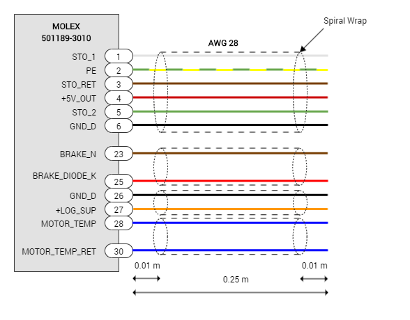
Input / Output Cable (C-PC-IO)
The Input/output cable is provided with a length of 250 m. It consists of a set of 11 x 28 AWG cables with a 30-pin Molex Pico-clasp connector on one side and flying leads on the other. Molex Pico-clasp connector should be plugged directly into the XCR J2 connector.
The cables are tie by means of spiral wraps in 4 different groups to simplify its identification:
- Safe Torque Off
- Brake
- Logic supply
- Motor temperature
| Side 1 - pin | Side 2 - pin | Wire color | Part Number | Signal | Function |
|---|---|---|---|---|---|
| 1 | Flying lead | White | 6820 WH005 | STO_1 | Safe Torque Off input 1 (positive, active from 5 V to 32 V, ISOLATED) |
| 2 | Flying lead | Green, Yellow Stripe | 6820 GY005 | PE | Protective earth connection, internally connected to standoffs and drive cold plate. |
| 3 | Flying lead | Brown | 6820 BR005 | STO_RET | Safe Torque Off common (optocoupler LEDs cathode, ISOLATED). |
| 4 | Flying lead | Red | 6820 RD005 | +5V_OUT | +5 V output, can be used for STO circuit. |
| 5 | Flying lead | Green | 6820 GR005 | STO_2 | Safe Torque Off input 2 (positive, active from 5 V to 36 V, ISOLATED) |
| 6 | Flying lead | Black | 6820 BK005 | GND_D | Digital signal ground, For STO group. |
| 23 | Flying lead | Brown | 6820 BR005 | BRAKE_N | Brake output (open drain with PWM capability) |
| 25 | Flying lead | Red | 6820 RD005 | BRAKE_DIODE_K | Cathode of the freewheeling diode for the brake, should be connected to the power supply of the brake. |
| 26 | Flying lead | Black | 6820 BK005 | GND_D | Digital signal ground |
| 27 | Flying lead | Orange | 6820 OR005 | +LOG_SUP | Logic supply |
| 28 | Flying lead | Blue | 6820 BL005 | MOTOR_TEMP | Motor temperature sensor input |
| 30 | Flying lead | Blue | 6820 BL005 | MOTOR_TEMP_RET | Motor temperature sensor return (referred to GND_D) |
Diagram
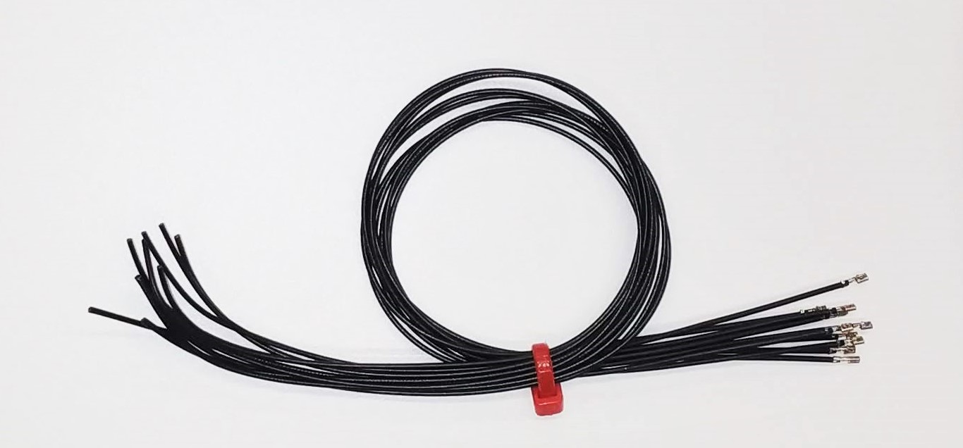
Extra wires for Feedbacks and Input / Outputs (C-PC-EXTRA)
Additionally, a set of 10 x 28 AWG cables with a pre-crimped Molex Pico-clasp socket on one side and flying leads in the other is provided.
These cables could be used to populate any specific functionality not provided in the C-PC-FEED or C-PC-IO connectors.